Continue to Site

Eng-Tips is the largest engineering community on the Internet

Intelligent Work Forums for Engineering Professionals

  • Congratulations cowski on being selected by the Eng-Tips community for having the most helpful posts in the forums last week. Way to Go!

Deck Edge Angle 3

Status
Not open for further replies.

Samwise Gamgee

Structural
Oct 7, 2021
118
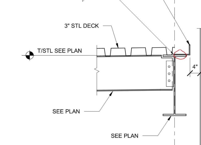
I have a 3" metal deck on roof. For the closure of the deck, I was planning on using an angle like shown in the picture. I have a couple of questions

[ul]
[li]Is it safe to say that the deck angle only acts as a chord member[/li]
[li]How do I design the weld between the edge angle and the deck ? I have seen it shown as 1/4" fillet weld at 3-12. I am assuming that means 3" per every 12" . What determines if this is adequate ? [/li]
[/ul]
2_ltoraf.jpg
 
Replies continue below

Recommended for you

They have bent sections to use as screed angles for most steel deck, and a simple 'puddle weld' to secure it. Is the angle part of the lateral load resisting 'deck plate'?

Rather than think climate change and the corona virus as science, think of it as the wrath of God. Feel any better?

-Dik
 
The edge angle and the beam are the chord at that edge when wind is perpendicular to it, and the collector when it's parallel.

I think you're confusing the connection of the deck to the angle with the connection of the angle to the beam. The weld you're describing is typically used for welding the angle to the beam. For it to work, the minimum thickness of that angle is 5/16". As for whether or not it is adequate, you need to run your loads through your load path, see what forces are acting on the weld, and design the weld for those forces. Connection of the deck to the angle will be as dik says - puddle welds or PAFs are the most common means of attachment of the deck to supporting structure. Spacing should be based on the requirements of uplift and diaphragm shear.

I just want to take a moment and be frank with you - "I'm assuming that means 3" per every 12""??? You're correct in your assumption, but based on previous posts you shouldn't need to assume that - you should know that if you've been given the responsibility of designing the structure you're designing. Everyone has to start somewhere, and you seem to be doing well - keep at it! - but for the love of all that is good in this world make sure you're getting a really thorough review from a senior engineer.
 
Thank you for the response. I need to make myself clear that I am not assuming that the weld works. I wanted to comprehend the detail before I was going to design it. And I also wanted to make sure that my understanding is correct. Unfortunately I am in a situation where my lead left and I all of sudden do not have anyone to guide me. So I am using this forum as a reference to perform my design correctly.
 
Is it safe to say that the deck angle only acts as a chord member

If it is welded to the beam? It will probably try to act like that and more (including as a built-up shape).

How do I design the weld between the edge angle and the deck ? I have seen it shown as 1/4" fillet weld at 3-12. I am assuming that means 3" per every 12" . What determines if this is adequate ?

Like phamENG was saying: follow the load path. Something else to consider (aside from the fact it could develop chord/beam type forces), is if this thing will also have to act as a toe plate. If so, you will have forces from that short cantilever as well. (I.e. the part of the angle that hangs out beyond the edge of the flange of the beam.)
 
Samwise - I understood what you meant. And I'm saying that's the sort of thing you should already know before you've reached this level. You didn't, and there's no changing that - but you do need to keep in mind you're moving a bit fast. Seems like you know that, and that's good. Hardest thing to learn is what you don't know.

We're all here to help and we enjoy doing it, but this forum is in no way a replacement for the review of an experienced engineer. Ostensibly somebody will be sealing the drawings when you're done. That person needs to guide you right now.
 
I also wanted to clarify a couple of things
[ul]
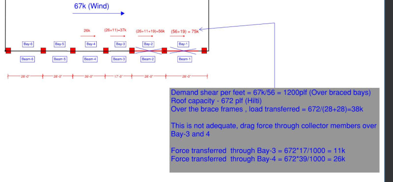
[li] For a composite beam design, I calculated the lateral load that needs to be distributed. Checked to see how much the diaphragm can transfer and added additional studs into the beams so that the loads gets dragged into the braced frames. Given the load was not much, I didn't need any collector bays here. When the load is in other direction, I am using the edge angle to behave like a chord member and checked the tension capacity and designed the weld. [/li]
[li]For roof framing, I calculated the lateral load that needs to be distributed. Checked to see how much the diaphragm can transfer and had to rely on collector beams bays to transfer the load. When the load is in other direction, I am using the edge angle to behave like a chord member and will check the tension capacity and designed the weld. One thing I am not certain is what is stopping the beams on Bay-6 and Bay-5 from collecting some lateral loads [/li]
[li]Also, am I understanding the collector forces correctly like I have shown in the screenshot[/li]

[/ul]


1_h5urqp.jpg
 
Do you actually need a closure angle in this situation? It can be helpful for attaching flush or bypassing stud walls but they can also be fastened directly to the beam.
 
If you want, you can apply welds to develop the pour stop, if it's previously been determined adequate.

For example, to develop 1/4" deck plate:
Fully developed bending force per inch (LRFD w/ A36 pl) = fb = M/Z = 4M/(L^2) = [4*0.9*36*((1.0*0.25^2)/4)]/(1^2) = 2.03 kips/in
What size, full length, fillet weld would be required to accommodate this load? fb/1.392= 1.46 sixteenths. Try 3/16" fillet welds
What percent utilization do we have: D_req/D_selected = 1.46/3 = 0.486 or 48.6%
So, per foot of length along the plate, you'd need 0.486*12 = 5.83 inches of weld metal (min) or 12 - 5.83 = 6.17 (max) of "gap".
w/ weld length of Ceil(5.83/2) = 3" (> AISC min length), space welds @ Floor(3in * 12 in/ft /5.83 in/ft) = 6" (as above)
So 3/16" fillet weld, 3" long @ 6" spacing.

I hope I didn't make a mistake in there. This is before second cup of coffee on the east coast.

Edit: This is an example and should not be arbitrarily applied to your specific case.
 
AISC Design Guide 22 is a good resource if you have any facade attachments to the slab edge.
 
Chords are usually continuous, so you will need a detail at joints between members. If you are dragging that force thru the connection, I would look at the member to do the heavy lifting. You can also use a light section if only a closure strip.
 
At the roof, I presume you have no concrete, right? You just need a chord member?

Normally, this chord is the beam row itself, not the edge angle, since the edge angle is not continuous. Those continuity forces need to be driven through the beam connections. I suppose you could make the angle continuous through field welding or bolting the ends together, but this would be unusual. In fact, that edge angle is usually turned down , not up, and the blocking at the roof edge is bolted through the angle. Check with you architect's details.
 
1) Bays five and six probably should be collecting some axial load.

2) My experience is the polar opposite of JLNJ's. In the markets where I've worked, the edge angles usually are designated the chords / struts and one of the goals of that is to avoid having to push axial loads through the beam line connections. The most common detail that I see for splicing the angles is to weld in a short segment of nested angle at the joints.

3) In my experience, the kind of stich welding that you are considering is ubiquitous and will be gross overkill in most conventional situations (chord / strut / light duty cladding attachment). My typical weld pattern is lighter than yours and, most of the time, I don't even bother to evaluate it numerically. On most projects, there will be much, much bigger fish to fry.
 
KookK , I am making it more complicated by trying to use edge angle as chord force and use the deck to beam attachment for the collector members. The issue is, it would be difficult to transfer the load into from Bay-5 to Bay- 4 without bending the HSS columns.

So instead if I used the edge angle to behave as collectors, I can get what size works and that should be enough to make them behave like chords as well in other direction. However, one last question I had is, the edge angle which now behaves as collector element, how does it dump the load at the braced frame ? Just based on the weld between the angle and the deck ?
 
SG said:
Just based on the weld between the angle and the deck ?

I assume that you meant to say the weld between the angle and the beams of the braced frames. If so then, yeah, that's exactly right. In these situations, it's usually the "dumping" that governs the weld design more so than the "collecting".

 
KootK , I was checking the weld and I believe I have plenty of capacity. Even if I use 3/16" weld (3@12). Weld Strength = 1.392*D*l = 1.392 * 3 * 3 = 12.6k per foot. My braced frames are 28' , so total weld over 28' will have12.6*28= 350k . That's way more that what I currently need . I only need to transfer 62k

So if I am using the edge angle as a collector element, shouldn't I weld the deck to the angles ? This will drag force from diaphragm/deck into the angles. And at the braced frames, I need to make sure the angle is welded to the beam so that it can dump all of the collected load. Is my understanding correct here ?
 
Can you use 1-1/2 @ 12? From notes:

-FOR INTERMITTENT WELDS, LENGTH SHALL NOT BE LESS THAN THE GREATER OF 4 TIMES THE WELD SIZE OR 40MM (1-1/2”). FOR COMPRESSION MEMBERS, THE MAX CLEAR SPACING BETWEEN WELDS SHALL NOT EXCEED 12”. FOR TENSION MEMBERS, THE MAX CLEAR SPACING BETWEEN WELDS SHALL NOT EXCEED 18” (CSA W59 11.4.13.2).


Rather than think climate change and the corona virus as science, think of it as the wrath of God. Feel any better?

-Dik
 

@Dr... good idea... I will add this to my programs in future.

Rather than think climate change and the corona virus as science, think of it as the wrath of God. Feel any better?

-Dik
 
OP said:
So if I am using the edge angle as a collector element, shouldn't I weld the deck to the angles ?

You can fasten the deck directly to the angles or you can fasten it to the beam and then have the shear load transfer from the beam into the angles. You just need to pick a load path and then follow it through logically.

OP said:
And at the braced frames, I need to make sure the angle is welded to the beam so that it can dump all of the collected load. Is my understanding correct here ?

Yes, that's right.
 
Status
Not open for further replies.

Part and Inventory Search

Sponsor