Continue to Site

Eng-Tips is the largest engineering community on the Internet

Intelligent Work Forums for Engineering Professionals

  • Congratulations cowski on being selected by the Eng-Tips community for having the most helpful posts in the forums last week. Way to Go!

Deck Edge Angle 3

Status
Not open for further replies.

Samwise Gamgee

Structural
Oct 7, 2021
118
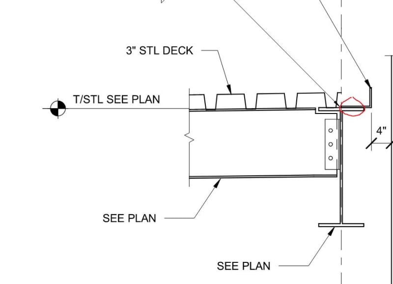
I have a 3" metal deck on roof. For the closure of the deck, I was planning on using an angle like shown in the picture. I have a couple of questions

[ul]
[li]Is it safe to say that the deck angle only acts as a chord member[/li]
[li]How do I design the weld between the edge angle and the deck ? I have seen it shown as 1/4" fillet weld at 3-12. I am assuming that means 3" per every 12" . What determines if this is adequate ? [/li]
[/ul]

2_ltoraf.jpg
 
Replies continue below

Recommended for you

If you specify for the decking to be fastened directly to the beam, and that deck to beam connection is sufficient to transfer your diaphragm shear, then the edge angle is rendered non-structural at least from a lateral force resisting element perspective.
 
lexeng18 said:
If you specify for the decking to be fastened directly to the beam, and that deck to beam connection is sufficient to transfer your diaphragm shear, then the edge angle is rendered non-structural at least from a lateral force resisting element perspective.

I feel that depends on the story the one wishes to tell. Often, when one seeks to avoid passing the collector load through the column connections, the story that is told is that the collector load remains within the angle. That matches reality somewhat over the columns because the angles will often be stiffest path there. What happens between the columns is, of course, another matter.
 
KootK - I'm interested in your nested angle detail. The squared edge of the nested angle and the fillet of the primary angle would cause a conflict. Do you go for a bent plate to splice it or have them grind down a rolled angle to fit?
 
KootK said:
That matches reality somewhat over the columns because the angles will often be stiffest path there. What happens between the columns is, of course, another matter.

Could you not just weld a piece of flat plate above the column from beam to beam to transfer the T/C and avoid the deck angle all together? (unless it is needed for attachment of C&C).
 
XR250 said:
Could you not just weld a piece of flat plate above the column from beam to beam to transfer the T/C and avoid the deck angle all together? (unless it is needed for attachment of C&C).

Sure, you could do any number of things. I believe that the original logic behind the nested angle detailing was was likely:

1) To allow the lengths of angle to be shipped loose and uncoordinated with respect to the column layout. Sometimes that's handy, particularly with OWSJ.

2) Sometimes, as you mentioned, an angle will already be present irrespective of the chord / strut business.

I have no beef with folks using the bare beams as the collectors in situations where that is a pragmatic solution. In fact, I like that better mechanically.
 
So having a continuous plate at the top of the HSS as shown in the screenshot can transfer the thru force ? I am not sure I completely agree with that here.

2_avsixg.jpg
 
OP said:
I am not sure I completely agree with that here.

It would likely be a loose plate that overlaps the flanges of both beams and is welded to them. Does that help? Obviously, it has to thick enough to not buckle when axially loaded unless it's welded to the column too.

One thing that I never love about this setup is that it tends to make an accidental beam moment connection at the joints. But, then, that is also true of:

1) A continuous angle.

2) Continuous topping rebar.

3) Most simple shear connections capable of transmitting axial.

...
 
This is what I currently came up with . Given that I have the option to increase the HSS thickness, I would rely on the beams to act as collector elements and the edge angle to act only as a chord element.

2_bdjeqg.jpg
 
OP said:
Given that I have the option to increase the HSS thickness, I would rely on the beams to act as collector elements and the edge angle to act only as a chord element

Sure. If the beams can be the collectors then why not also make them the chords?

Another way to get around the issues at the HSS walls is to bypass them with either a through plate or a WT. Both of those solutions have their own associated costs of course.

 
KootK , I understand why it would be beneficial to use beams as chords as well. That way I do not have to rely on the edge angle to be continuous (as it no longer acts as a chord member) . This is ideal because I have multiple columns which interrupt the edge angle.

I am trying to understand what I need to do to use the beams as collector elements. The beams are already connected to the deck. So I just need to check the chord force as compressive/tensile force in the beams right. As the beams can take a significant amount of axial force, why would be ever use edge angle as a chord member then ?

I have a chord force of 55kips . I was also considering just rebar to resist that chord force . So it would be close to 5-#4 bars.
 
Samwise Gamgee said:
So I just need to check the chord force as compressive/tensile force in the beams right. As the beams can take a significant amount of axial force, why would be ever use edge angle as a chord member then ?

This topic always gets a bit awkward for me as I wind up espousing ideas that I don't entirely agree with myself. Ahhhh well... reasons to use an angle:

1) Similar to what you've dealt with here, passing the axial load through an HSS column economically can sometimes be a challenge.

2) Often it's desirable to have short slotted holes in these connections for erection. To use those same holes for axial load, you then have to go and make them slip critical which adds cost, mostly inspection cost.

3) As I mentioned earlier, there are situations with OWSJ joists that lend themselves to the use of edge angles:

a) in roofs edge angles are often there for parapet support anyhow.

b) depending on what you're doing for joist rollover, you might want intermittent HSS lugs with angles continuous and welded to them.

c) roofs often have overhangs which tends to move the edge of the deck outboard of the main support lines. Some folks want the chord element at the extremity of the deck no matter what.

4) Once one says that the axial loads are in the beams, what does that mean when those beams change depths along the line, as they often do? Are there eccentricities that ought to be designed for? Probably.

5) Designing the beams as beam-columns for strong axis is no big deal as you've said. However, depending on your deck type, deck direction, and disposition of discrete bracing elements, sometimes designing the beams as beam-columns for weak axis buckling can be a challenge and add beam weight. Some folks will use the deck angles to address that by telling stories of this sort:

a) If the beam is capped with a member that can deal with the weak axis buckling on it's own, then the beam doesn't need to deal with it.

b) If the beam is made composite with a member that can deal with the weak axis buckling on it's own, then the resulting composite shape must be good for weak axis buckling.

Like I said, I don't believe everything about every structural engineering story that I've ever been told. These are the narratives that you hear out in the wild however.

OP said:
I was also considering just rebar to resist that chord force . So it would be close to 5-#4 bars

Hell yes, rebar is generally my first choice if there's a concrete deck kicking around. My only concern with with the rebar approach is that folks often wind up designing that to the max based on AsFy. If one extrapolates that result out to study the axial strain that it implies, sometimes that number is uncomfortable. When I do collectors in rebar, I often proportion them for strain rather than strength.
 
Have a look at your firms typical details for beam connections to HSS columns. Most--if not all--drawings I've seen from CA firms use through plate connections, in which case it makes sense to use the beams as chords / collectors since there is already a continuous load path along the collector line.
 
I was designing a slip critical connection and was advised that I do not need it. That I can just have standard holes called out. Which makes me wonder, shouldn't I add at least Short Slotted Holes on one side of the beam ?

 
Deker said:
Most--if not all--drawings I've seen from CA firms use through plate connections, in which case it makes sense to use the beams as chords / collectors since there is already a continuous load path along the collector line.

Will that also be the case for low beam connections on, say, two story columns? I've always imagined the slotting to be difficult to fabricate unless it's at the top of a column. But, then, what I don't know about steel fabrication is... a lot.
 
Samwise Gamgee said:
I was designing a slip critical connection and was advised that I do not need it. That I can just have standard holes called out. Which makes me wonder, shouldn't I add at least Short Slotted Holes on one side of the beam ?

Not if you are relying on the beams and shear plates to act as collectors since the axial force load path would be parallel to the slots. While the connection may be designed as bearing, AISC 341 requires that the faying surfaces be prepped as slip critical.

KootK said:
Will that also be the case for low beam connections on, say, two story columns? I've always imagined the slotting to be difficult to fabricate unless it's at the top of a column. But, then, what I don't know about steel fabrication is... a lot.

The fabricators I've worked with have told me it's not a big deal to slot in one direction. The perpendicular beam connection would stop at the face of the column. If you need to pass load through both directions, the through plate option requires a column splice above the connection. In that case you either eat the cost of the splice or, ideally, switch to a wide flange column.
 
Instead of a slip critical connection, I decided that I will have short slotted holes (to make erection easier). And then, I will weld the shear tab at the top and bottom after the bolts are attached so that it can engage the axial load without relying on the slip critical connection. I think the load path works best here. The only catch being , I will have a connection which is bolted and welded.
 
Samwise - slip critical would be the less expensive option here. Those welds are field welds and will be part of your seismic force resisting system, meaning they'll have some pretty strict NDT field testing requirements. Specify DTI washers or tension control bolts and the cost of inspecting a slip critical connection should be lower and easier to analyze. If you're going to weld it, then show an erection bolt to assist alignment and put everything in the welds.
 
Are those forces all additive? Could be, but just to make sure.

Rather than think climate change and the corona virus as science, think of it as the wrath of God. Feel any better?

-Dik
 
phamENG, great point. Yes , once the beams are erected I was going to design the welds to take the gravity/ lateral loads. The bolts would be sacrificial , but its a small cost over other alternative.

dik, the forces are additive. But the tricky part is the load combination. So I will never have factored wind and factored dead load at the same time.
 
Status
Not open for further replies.

Part and Inventory Search

Sponsor