Hello everyone,
I am facing a problem that I have troubles resolving.
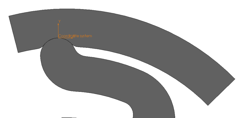
I am doing a 2D contact simulation between 2 parts :
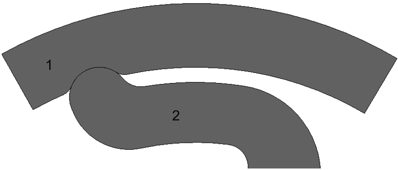
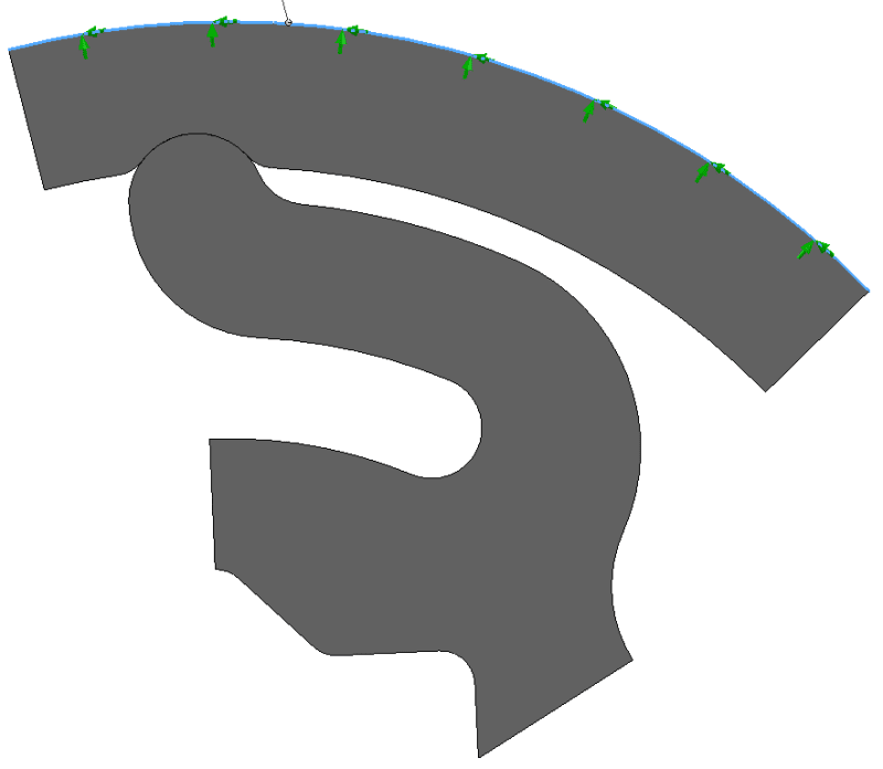
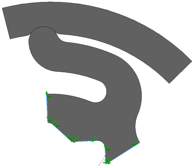
Part 2 is constrained at the base. Part 1 has an imposed angle & also a pivot linkage relative to the center of rotation.
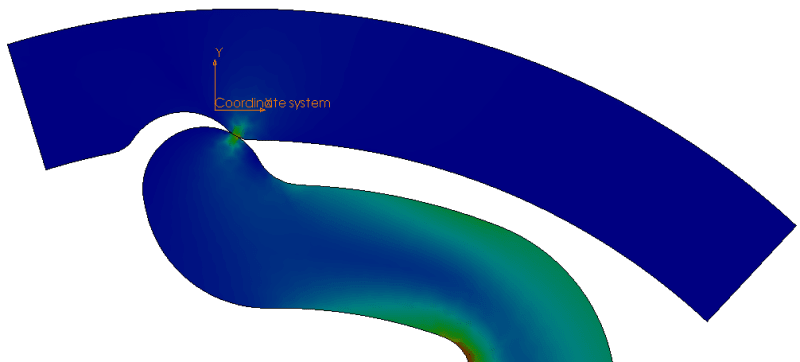
Here is the end result:
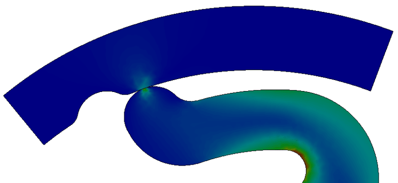
Now what I am trying to recover is the torque generated by part 1 on part 2 (or vis-versa, doesn't mater).
At the moment, the only way I found to do so is exporting the resultant forces and multiplying it by the lever arm but I have no confidence in the force I am reading. I have tried to plot the forces on 3 different coordinate systems al of which have an X axis that is orthoradial, but this gives me 3 different results so I am a bit lost...
Coud anybody tell me which value I should extract in that case to deduce the torque in the system ? Or is there a way to directly have the torque ? Is there a tutorial I could follow somewhere ?
Thanks to whoever can help on this")
Have a great day.
I am facing a problem that I have troubles resolving.
I am doing a 2D contact simulation between 2 parts :
Part 2 is constrained at the base. Part 1 has an imposed angle & also a pivot linkage relative to the center of rotation.
Here is the end result:
Now what I am trying to recover is the torque generated by part 1 on part 2 (or vis-versa, doesn't mater).
At the moment, the only way I found to do so is exporting the resultant forces and multiplying it by the lever arm but I have no confidence in the force I am reading. I have tried to plot the forces on 3 different coordinate systems al of which have an X axis that is orthoradial, but this gives me 3 different results so I am a bit lost...
Coud anybody tell me which value I should extract in that case to deduce the torque in the system ? Or is there a way to directly have the torque ? Is there a tutorial I could follow somewhere ?
Thanks to whoever can help on this
Have a great day.