Eng-Tips is the largest engineering community on the Internet

Intelligent Work Forums for Engineering Professionals

  • Congratulations waross on being selected by the Eng-Tips community for having the most helpful posts in the forums last week. Way to Go!

Deep beam support length

Status
Not open for further replies.

Jummybear

Civil/Environmental
Jul 24, 2014
10
EE
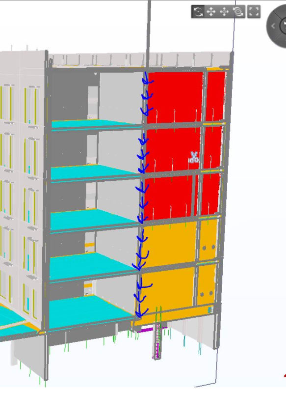
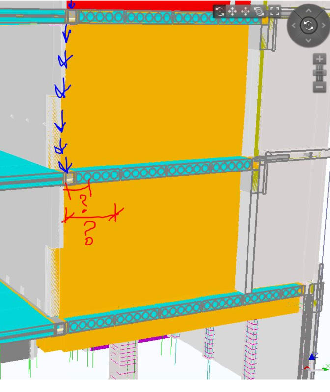
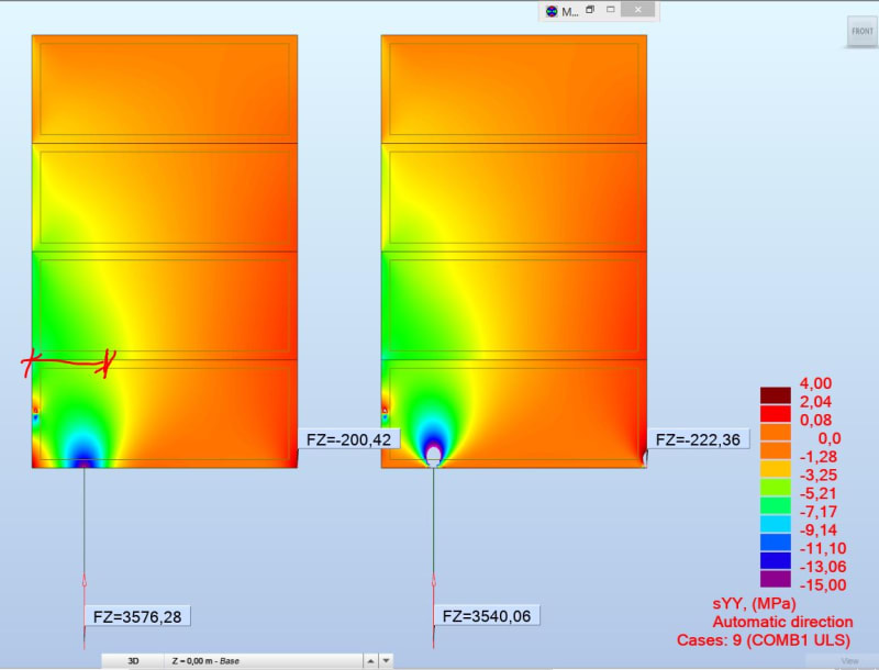
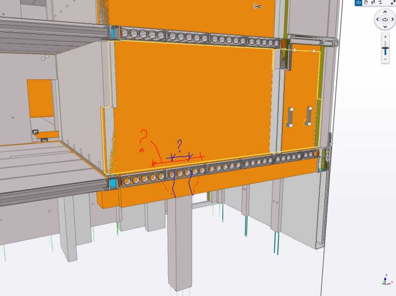
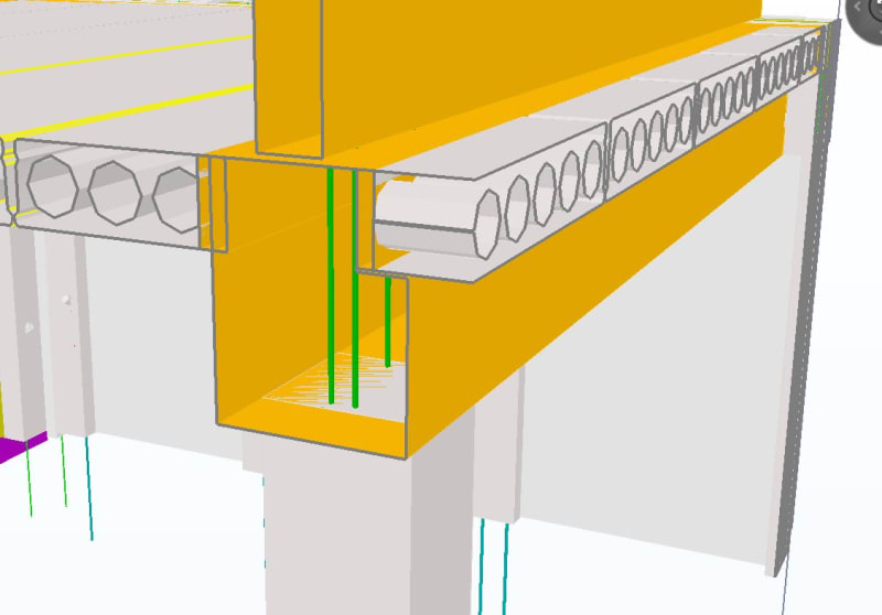
I have to design some deep beams (walls) in my ongoing project. I have a problem with determining appropriate length of support. I will attach a picture. Between deep-beam and concrete column there is a concrete beam for supporting hollow core slabs on first floor. What would you suggestion for length of the support? Length on the column look very conservative, probably something between 25-45 degrees?

Capture2_hhoedd.jpg
 
Replies continue below

Recommended for you

45 degrees strikes me as pretty reasonable. I probably wouldn't bother to distribute through the hollow core which, I assume will be grouted at the ends beneath the wall.
 
KootK
Thanks for reply. We do not distrubute anything through hollow core slabs, its a ledge concrete beam there, so wall will transfer compression directly to beam body.
Capture3_zmymy6.jpg
 
Are there dowels connecting the wall to the beam? Just thinking those dowels would be trying to enforce (unintended) deflection compatibility/composite action between the wall and beam.
 
bones206 said:
Are there dowels connecting the wall to the beam? Just thinking those dowels would be trying to enforce (unintended) deflection compatibility/composite action between the wall and beam.

1) Definitely if it's CIP.

2) Maybe not if it's precast, as I expect, although there would be some form of connection for sure.

3) A related issue that crossed my mind is that, even in the absence of a connection, the deflection pattern of the beam may well affect the way in which load is transmitted to the wall at the bearing points. Whether the cantilever rotates up or down etc. In this respect, a stiff beam is helpful. In practice, I usually turn a blind eye to these more arcane concerns: stuff that is difficult to assess, slows me down, and seems to rarely cause real world problems.
 
45 degrees gets my vote.

Assuming the wall is reinforced insitu concrete - You’ll likely find that the wall is so stiff that the “beam” is doing very little.
 
KootK said:
In practice, I usually turn a blind eye to these more arcane concerns: stuff that is difficult to assess, slows me down, and seems to rarely cause real world problems.

Yea, same here. I know I’m overthinking it but for some reason the question nibbled on my brain and I figured I’d throw it out there. I can’t put my finger on exactly what my concern would be, but I seem to recall a condo building in Australia in the Engineering Failures and Disasters forum that had some issues with unintended load paths and localized overstress in precast walls: thread815-447605. Might be what was tickling the back of my brain. I believe in that case the designer may have treated the wall as uniform load on the beam, rather than as a deep beam with discrete bearing points as the OP is doing.
 
bones206 said:
Are there dowels connecting the wall to the beam? Just thinking those dowels would be trying to enforce (unintended) deflection compatibility/composite action between the wall and beam.
Yes, there will be dowels.

KootK said:
1) Definitely if it's CIP.

2) Maybe not if it's precast, as I expect, although there would be some form of connection for sure.

3) A related issue that crossed my mind is that, even in the absence of a connection, the deflection pattern of the beam may well affect the way in which load is transmitted to the wall at the bearing points. Whether the cantilever rotates up or down etc. In this respect, a stiff beam is helpful. In practice, I usually turn a blind eye to these more arcane concerns: stuff that is difficult to assess, slows me down, and seems to rarely cause real world problems.

1. It was precast wall/beam in the begining (we took this project over from another engineering company), but then we decided to make 2 first walls as CIS and beam is also CIS. Column in precast one. Wall thickness was 200mm, we are deciding now to leave it 200, make 250 or even more.
2. Answered above in p.1
3. Can you explain a little bit more? The wall is way more stiffer than beam, so in my mind it doesnt really matter how stiff beam will be - the real behaviour of the beam, which would be "pinched" between supports under and stiff wall above, would be dictated by these 2 aspects + keep in mind that there will be dowels between, so they will act as a composite (there will be a pouring joint between wall and beam).

bones206 said:
Yea, same here. I know I’m overthinking it but for some reason the question nibbled on my brain and I figured I’d throw it out there. I can’t put my finger on exactly what my concern would be, but I seem to recall a condo building in Australia in the Engineering Failures and Disasters forum that had some issues with unintended load paths and localized overstress in precast walls: thread815-447605: Opal Tower - Sydney Australia. Might be what was tickling the back of my brain. I believe in that case the designer may have treated the wall as uniform load on the beam, rather than as a deep beam with discrete bearing points as the OP is doing.

Thanks to poiniting to that thread. As I am very rare guest on this forum I didnt know about it. Looks very interesting topic but I dont have time to read whole thread right now :( Anyway problem looks +/- the same - supporting slender wall on concrete column or vice versa.

Just some more inputs on my project: its a 6-floor building + 1 basement floor. According to preliminary static calcs and my STM assumptions, deep wall acts as a cantiliver. So I have one main compression strut and my tie (tension) looks like an arch. Thats because loads from upper floors mainly aplied to upper left corner. Bearing side wall (in gray colour) also transfer half of its load to my orange bearing wall directly through the vertical joint at each floor. So finally there is a lot of space in beam to place tension reinforcement but my tensoin in deepbeam/wall will acuur on the opposite wall side :)

One more question related to this topic. My STM calculation checks are mostly goverened by local stess checks/limits and also strut width assumtion is not so easy for me. The main problem is in main comression strut that fail check all the time. When I take wider support and more length for line load distribution which comes from upper floors then it begins to converge. The question is what is the line load length on your opinion is apropriate and safe to take into account? I was started, again, very conservatively from 200mm, but this doesnt make sense even for me. Some more pics are attached to this post. I also have modelled all walls together with beam and looked at compression stress flow, like an alternative solution to my 200mm I have tried in the begining. Picture attached. Thanks again guys for you thoughts, really appriciated.

PS Picture with compression stress flow is from another wall, but its pretty similar to this one (wall is on the opposite side of the building), slightly another position of the column and floors are 5 instead of 6.

Capture4_e4emxd.jpg

Capture5_m72g2e.jpg

Capture6_zbsvcy.jpg
 
Status
Not open for further replies.

Part and Inventory Search

Sponsor

Back
Top