Hello everyone,
I am analyzing a steel SHS truss, with am applied displacement at the tip. The truss displacement is laterally constrained and in that same sections, springs were modelled to simulate the fact that in a previous experimental test the lateral constraining system was at a certain distance from the truss. What I want to achieve is the load-displacement curve at the point where the displacement was applied.
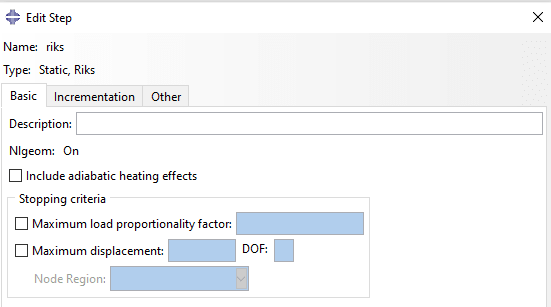
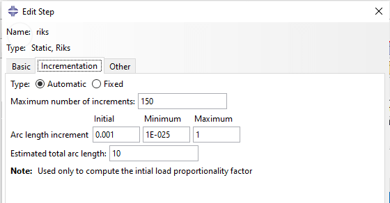
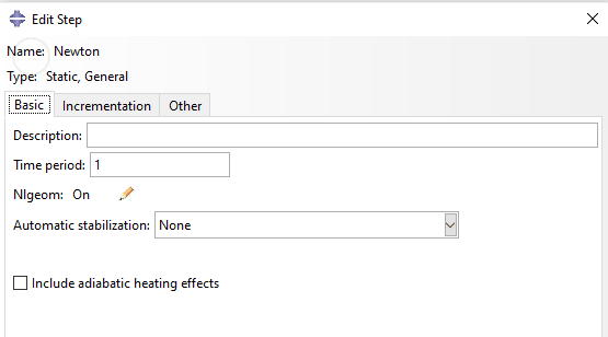
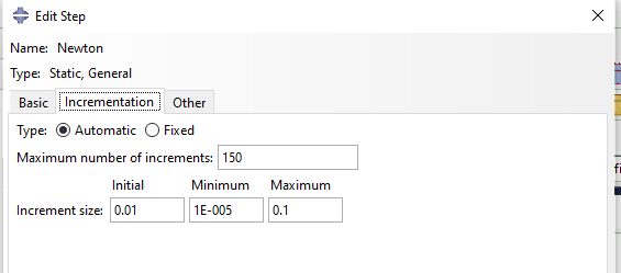
Since I want to include nonlinearity in the model the step I used was RIKS, static. But I also analysed the model with a General, static step and came to the conclusion that for the same applied displacement and a maximum number of increments, the truss where a general step was used presented a bigger vertical displacement, which I also want to achieve through a Riks step. Did this happen because of the way I modelled the Riks step?
I will leave some images for a better understanding.
Thanks in advance!
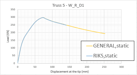
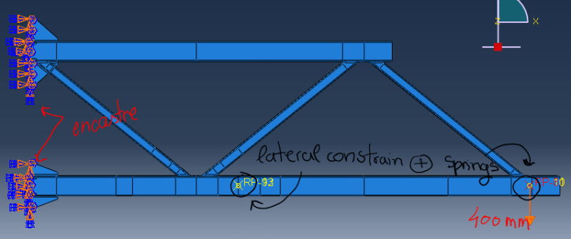
I am analyzing a steel SHS truss, with am applied displacement at the tip. The truss displacement is laterally constrained and in that same sections, springs were modelled to simulate the fact that in a previous experimental test the lateral constraining system was at a certain distance from the truss. What I want to achieve is the load-displacement curve at the point where the displacement was applied.
Since I want to include nonlinearity in the model the step I used was RIKS, static. But I also analysed the model with a General, static step and came to the conclusion that for the same applied displacement and a maximum number of increments, the truss where a general step was used presented a bigger vertical displacement, which I also want to achieve through a Riks step. Did this happen because of the way I modelled the Riks step?
I will leave some images for a better understanding.
Thanks in advance!