Continue to Site

Eng-Tips is the largest engineering community on the Internet

Intelligent Work Forums for Engineering Professionals

  • Congratulations SDETERS on being selected by the Eng-Tips community for having the most helpful posts in the forums last week. Way to Go!

Defining Earthquake Directions

Status
Not open for further replies.
Feb 19, 2009
28
Hello all,

I have a question about defining eartquake loads:

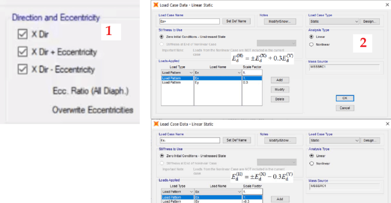
1) In some Etabs tutorials, directions are defined like in the first part of the picture (1) : X Dir, X Dir+Ecc, Y Dir+Ecc all selected in one load pattern.

2) And in some other examples there are 3 different Load Patterns: EX, EXp and EXn (and Load Cases with the same words) (By the way, I am talking about only X direction. It is same for Y directions too.)

3) And in some other ones like this one, there are 2 different Load Patterns : EXP and EXN.

4) Except the ones above, there is one more option like in the second part of the picture (2) I think. (By the way the screen from Sap2000 but the logic is the same I think.)

So, my question is: Which options are OK? Which ones are not correct? Which ones are the best options?

Could you please help me about this confusion?
EngTips-ExExpExn_ha7sko.png


Regards,
Latif
 
Replies continue below

Recommended for you

Depends on the code provisions, usually codes prescribe for static analysis 100% load in one direction and 30% of load in the other direction orthogonal to the first one. Also, normally codes forse you to apply an accidental eccetnricity (for example 0.1 of the diaphragm dimension perpendicular to the load direction, in Autsralia) to your static loads.

So the correct thing to do in ETABS is to tick only the second and third (Dir+Ecc and Dir-Ecc) which means it will run the case with positive eccentricity and the case with negative eccentricity. The case with no eccentricity has no use, normally. You can choose to tick that one too, it simply won't ever govern your design or checks. You then need to do the same for the Y direction. And finally you need ot combine them with gravity loads (again as per your code, often it is 1.0G+0.3Q) plus all permutation between EX and 0.3 EY and all permutations between EY and 0.3 EX

So to sum up your patterns in ETABS will be

EX:
X Dir + Eccentricity
X Dir - Eccentricity

EY:
Y Dir + Eccentricity
Y Dir - Eccentricity

Lead load cases as automatically created by etabs when you define the load patterns and then you need to define the design combinations as follows
G+0.3Q+EX+0.3EY
G+0.3Q+EX-0.3EY
G+0.3Q-EX+0.3EY
G+0.3Q-EX-0.3EY
G+0.3Q+EY+0.3EX
G+0.3Q+EY-0.3EX
G+0.3Q-EY+0.3EX
G+0.3Q-EY-0.3EX
(the above is valid if the code prescribes G+0.3Q, otherwise you need to apply the factors as per your code)

ETABS will always automatically associate eccentricities so they always produce the worst case (summing positive with positve and negative with negative), so for each combinaiton you will have 2 steps (one ofr positive and one for negative eccentricity)
 
Thank you so much for your answer. In tutorial I watched it load pattern was defined like the picture number one above. And load combinations was defined like the picture below. As an example, for 0.9G±E, only 8 load combinations should be enough. But the picture below says we have to define 8x9=72 load combinations. But according to your answer, we dont need to do that and only 8 combinations would be enough.

The tutorial takes X dir (0.00 exc.) into considetation (maybe codes says so) too. And maybe that is why 8x9=72 total combinations needed. I will be glad if you have any more comment about it.

Soru-Sap_Etabs-Kombinasyonlar-0.9G_E_i2xhew.png
 
Status
Not open for further replies.

Part and Inventory Search

Sponsor