willindsey
Aerospace
- Apr 18, 2023
- 7
Hello,
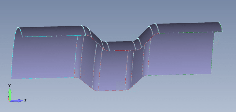
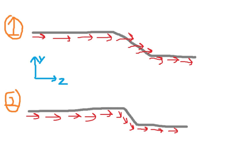
Currently modeling a 1/8 slice of a cylinder with a center constriction. This is a smaller model to understand the material orientation changes and tools with in FEMAP. I'm currently stuck on how to go about defining the material coordinate system in both 2-D and later 3-D (extruding elements). For the 2-D case, I have set the material direction choosing cylindrical coordinates and aligning the orientation in the +Z direction (this is the intended 0 degree fiber orientation). There is uncertainty in the center transition. Open to tips and approaches to define and create the correct material coordinate system. Can this be accomplished with the material orientation tool or do multiple coordinate systems need to be defined to account for the radii and the tapper? Eventually going to work towards a 3D model, but that seems to be a can of worms. Thank you!

Currently modeling a 1/8 slice of a cylinder with a center constriction. This is a smaller model to understand the material orientation changes and tools with in FEMAP. I'm currently stuck on how to go about defining the material coordinate system in both 2-D and later 3-D (extruding elements). For the 2-D case, I have set the material direction choosing cylindrical coordinates and aligning the orientation in the +Z direction (this is the intended 0 degree fiber orientation). There is uncertainty in the center transition. Open to tips and approaches to define and create the correct material coordinate system. Can this be accomplished with the material orientation tool or do multiple coordinate systems need to be defined to account for the radii and the tapper? Eventually going to work towards a 3D model, but that seems to be a can of worms. Thank you!


