VN1981
Aerospace
- Sep 29, 2015
- 186
Hi Folks,
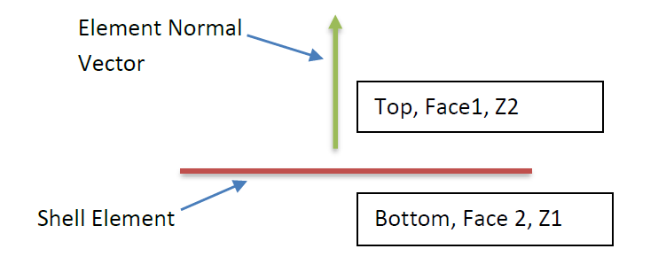
I was trying to get a better understanding of definition of various shell/plate element terms (Z1, Z2, Top, Bottom, Face 1, Face 2). I did a simple case study of a cantilever plate subjected to transverse load. Basically put the plate in bending. Did the case study in two FEA packages: MSC Patran & Femap. Based on the output and verifying via the software, I was able to get some clarity on the definition of the above terms with respect to Shell Element Normal Vector. I have created an illustration of the same. Would love to hear feedback from other users on its accuracy.
Regards,
- VN
