Eng-Tips is the largest engineering community on the Internet

Intelligent Work Forums for Engineering Professionals

Deflection for a Combined Foundation 3

Status
Not open for further replies.

XinLok

Civil/Environmental
Oct 22, 2019
74
0
0
QA
I am trying to get the deflection D(x) under a combined foundation.
Screenshot_2024-03-05_at_1.30.15_PM_plhedc.png


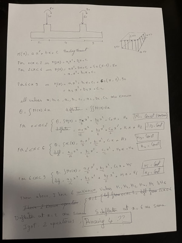
I manage to get the function bending moment M(x) by dividing the area in 3 places.
- Equation 1: from Edge of foundation to First Column C1
- Equation 2: From Column C1 to Column C2
- Equation 3: From Column C2 to the edge of foundation

by integrating the differential equation of the deflection Curve, I got the function deflection(x) but with 6 unknowns parameters (Const1, Const2, Const3, Const4, Const4, Const6)

in order to solve these unknown const, I should have 6 equations.
But what I have is just 2 equations.
the First one: Deflection from Equation 1 at C1 = Deflection from Equation 2 at C1
Second one: Deflection from equation 2 at column C2 = Deflection from equation 3 at column C2.

how to get the remaining 4 equations.

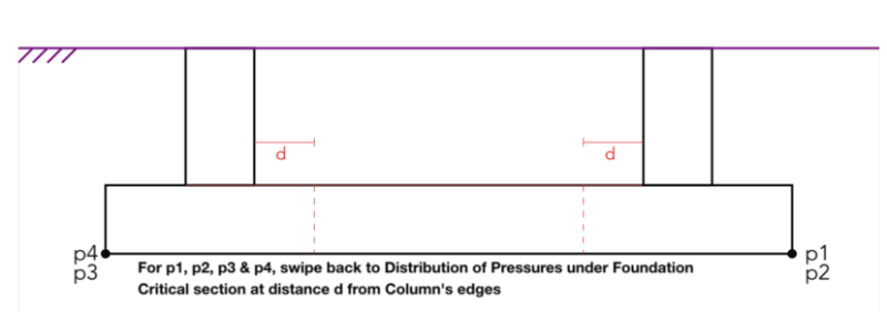
I cannot consider the deflection at column 1 and column 2 = 0 cause underneath is soil.

any advise or help so I can proceed cause I already stuck for almost 1 week.
 
Replies continue below

Recommended for you

Seems to me, if you want the deflection of the foundation, you need to know (or assume) the elastic properties of the soil as well as the properties of the concrete. Maybe you have this covered?

You are using the same symbol for constants of integration and column numbering...very confusing.

I don't know if this is even appropriate, but have you tried using the Macauley system to eliminate four integration constants?

I don't understand your comment about p1 to p4 (swipe back to Distribution of Pressures...etc.). Can you indicate how these four pressures are calculated using your method? If you are neglecting the soil stiffness, deflections should be easy to calculate using normal methods, but they neglect a significant variable.
 
Old school method:

1) Proportion the footing in plan as rigid such that you have uniform soil stress under permanent load.

2) Assume that you have whatever settlement your geotechnical report said you'd have under q_allow.

3) If you're feeling fancy, work out the footing curvature between columns and proportion the footing depth to keep that value inconsequential.

There's little to be gained by getting math/FEM fancy on conventional foundation elements. Any minor slop in analysis technique will often just become signal noise relative to the uncertainty inherent in the soil properties and the cracked concrete stiffness. If you need precision, get into building pianos.
 
Thanks gentlemen for your reply,
I changed the constants as you were right, it was confusing using the same numbers.
I got the pressure by using P / A + P * Ye / Ix * y + P * Xe / Iy * x and then using the Chart Ten to calculate K in case there is tension beneath the foundation.

The way I did is not correct?
I did not understand quite well from the comments above, however I am going to go through it in more detail but doing some search.
but is there a know method I can use? cause I don't know what is the old school method.

 
Are you dealing with a combined foundation with biaxial bending moments?

If so beam on elastic foundation won’t be appropriate and you’d need to go to an FEM solution if you want to consider any flexibility of the foundation.

If flexibility of the foundation is not a concern then once you have the bearing pressure then you have all the information you need to form shear and moment diagrams for the foundation system from your sketch. Consider rotating your image 180 degrees and thinking of the bearing pressure as an applied distributed load, the columns as pin supports, and any column moments as concentrated moments. This reduces the model to a statically determinate beam with a cantilever on either end and the internal forces can be solved through section cuts and statics alone.

To address your biaxial bending condition each section through the rigid foundation will produce a shear, moment and torsion resultant at the cross section centroid. Again though your system is statically determinate so all the information to form the internal resultant is available without any compatibility equations.
 
Thanks Celt83, yes I am dealing with Biaxial bending moment.
I already have the Shear and bending moment diagram V(x) and M(x).

If I consider the 2 columns as pins I think I can solve the remaining 4 equations, but can I consider the columns as pins? cause for sure there will be settlement over there. in this case I am considering the deflection on columns is zero which I believe it is not.

Is there a method to consider the ground under the foundation as many springs (distributed each 50 cm) and then get the deflection on each spring?
I am asking this cause I am not sure if it can be done in such way.
 
What is it you are trying to solve for, your initial post indicated you were trying to form the moment equations but your last post you say you have the moment functions?

Anything to do with settlement or spring supports of a biaxially loaded combined foundation you’ll want to use an FEM solution.
 
I need to get the deflection function D(x)
from M(x), I get the deflection function D(x) by doing ∬ M(x)
In the deflection functions D(x), I got 6 unknowns values (Const1, Const2, Const3, Const4, Const4, Const6) and I need to know those values

to solve those 6 unknowns values, I need 6 equations.
in my initial post, I got two equations and remaining 4 equations in order to be able to solve the values of Const1, Const2, Const3, Const4, Const4, Const6.

for using FEM, I want to start learning it. but is there any useful tutorial about it?
 
That method is not appropriate for a foundation.

If you had uniaxial bending you could do beam on elastic foundation:
EI dy4/dx4 + ky = q

For the biaxial bending case it is a two-dimensional problem and generally best solved with the finite element method.
 
Thanks a lot Celt83 for all your replies, lets consider it first as one uni-axial moment.
by using EI dy4/dx4 + ky = q, I will get 6 unknown values to be identified.
to solve them, I need to have 6 equations. is that correct?
 
Fuck me, maybe I'm stupid but this all makes no sense to me
I can't see any loading presented on the diagram, is this axial only or is there some sort of shear/bending demand at the base?

Why the heck are you trying to do this by hand in the age of computer software?
Not that I don't admire and recommend hand calcs...it's just the some things the computers really are better at
Surely this should be a soil-spring model with a range of properties applied to both the footing stiffness and soil stiffness

I imagine that you will find (for axial anyway) a very uniform distribution of load at the underside of the footing
In which case you could have conceptualised this model as a double-support beam with overhangs at both ends, the soil reaction as a UDL on the beam, and the support reactions being your applied axial loads
There are standardised formulas for this to estimate the deflection of the beam (foundation) which you could apply for a simple model
 
@BAretired thanks a lot, yes with Macaulay's method I can solve the 2 unknown constants, but I need to consider that the displacement below the 2 columns are zeros.
Is it correct to consider the deflection underneath the two columns are zero?
 
For a uniformly loaded beam on elastic foundation there are (4) integration constants defined by the boundary conditions:
y0 ( x ) = ch α x [ C 1 cos α x + C2 sin α x ] + sh α x [ C3 cos α x + C 4 sin α x]

ch α x --> hyperbolic cosine of α x
sh α x --> hyperbolic sine of α x

Roark's has tables for the for various loading conditions of finite-length beams on elastic foundations (Table 7 in the 5th Edition).
 
you can't compute deflection that way for a beam on soil, the soil reaction is coupled to the deformation.

why are you trying to compute deflections anyway?
 
If you absolutely must know the deformation then you need to get the settlement information associated with your bearing pressure from the geotechnical engineer.

If you are determining bearing pressures from the rigid base assumption and using P/A +/- M/S then the settlement follows rigid body motion and the only consistent means of determining settlement would be to ratio your corner settlements based on their respective bearing pressures and then the settlement at any interior point would found via bi-linear interpolation from the corner values. Any other means of determining settlement would be inconsistent with the rigid foundation assumption used to determine the bearing pressure.

If you want to consider the foundation flexibility and only have uniaxial bending then you can do a beam on elastic foundation analysis.

If you want to consider the foundation flexibility and you have biaxial bending then you must do a finite element analysis.
 
XinLok said:
I got the pressure by using P / A + P * Ye / Ix * y + P * Xe / Iy * x and then using the Chart Ten to calculate K in case there is tension beneath the foundation.

If this is the way pressure is being calculated, the foundation is not being designed as a beam on an elastic support. It assumes that the foundation is rigid relative to the soil supporting it. I'm pretty sure that is the way most engineers would approach the problem. I know I would.

It is not necessary to create a single expression for the entire length of beam which entails two cantilevers and a span. Simply design each cantilever for the calculated soil pressure and resulting moment. The span is just a simple beam with a moment applied at each end. That is the "old school method" and perfectly adequate for the current application.

It is far better to understand the design you are doing than to mess about with theory which is beyond you. And "when in doubt, make it stout".
 
Status
Not open for further replies.
Back
Top