Continue to Site

Eng-Tips is the largest engineering community on the Internet

Intelligent Work Forums for Engineering Professionals

  • Congratulations cowski on being selected by the Eng-Tips community for having the most helpful posts in the forums last week. Way to Go!

Deflection of a beam supported by two other beams

Status
Not open for further replies.

SC83

Mechanical
Jun 8, 2018
24
Hi,

I want to calculate the deflection of a beam (tube) with a uniform load that is applied over a length Ww. The tube is supported by two other (smaller) rolls (see layout in the image below). All three rolls are mounted in a bearing at the end. How can I do this?
beam_a2xy33.png
 
Replies continue below

Recommended for you

There was a real long thread about something similar to this (but wood construction a while ago).

How accurate of an answer are you after? Personally I'd be using the moment of inertia of the two lower rollers only if you just need to get within a comfortable range.
 
Is the tube connected at all to the round bars below, or just bearing? Are the round bars tied together laterally? The bottom bars will want to separate as they deflect downward if they aren't connected.

I agree with jayrod, first step for me would be to check just the two bars below, if the results are reasonable then there is no need to dig further.
 
I would start by drawing a FBD of the structure.

I expect that all three tubes will deflect the same. I think the top tube will bend, being supported by the lower two tubes, which will also bend. Depending on the relative bending stiffness, it's possible that the ends of the upper tube may lift off the lower tubes.

I don't see the three tubes working as one integral section (that would require a shear connection between them as the upper tube would have a net compression load, balanced by a net tension load in the lower tubes. I see the moment being distributed between the three tubes (less conservative than above suggestion)

another day in paradise, or is paradise one day closer ?
 
Assuming the tube is not connected to the supporting rollers and ignoring friction between them, it's a matter of summing the individual moments of inertia of the 3 sections to use as the "I" of a single simply supported beam. The harder part may be finding a formula for deflection of the "effective" beam with a partially distributed uniform load.
 
This is all discussed in detail in the previous thread:

Or for a summary and (my) conclusions see:


Doug Jenkins
Interactive Design Services
 
Steven C:
How about fleshing out your problem with much more real world engineering info. and detail. Put real sizes and dimensions, thicknesses, loads, forces, some info. on bearings, etc. on your sketch. Then, you might get some serious discussion instead of wasting our time with more 20 questions and elementary textbook cartoons. Tell us a little about what it is and how it works, so we can understand what you are actually doing. Looks like a plate roll to me? Then, the load on the top roll is in the wrong direction, even though its magnitude may be o.k. and be the sum of the two vert. reaction components from the lower two rollers. I think you have a beam on an elastic foundation problem (a beam on springs), with the spring rate and spacings and locations being a function of the relative stiffness of the top roller vs. the stiffness of the two lower reacting rollers. Doug Jenkins’ links are a good place to start.
 
If the top roller tube was not the full length of the span, the discussion linked to by IDS would definitely be pertinent. The sketch appears to show all 3 bars extending the full length of the span, with a load applied to the top of the top tube. I assumed it was just a simple support roller for a plate of some kind going over the top. If those 2 assumptions are true, the problem is fairly straightforward - "I" for the system is the sum of the individual "I"'s of the 3 members. All that's left is to find or derive a formula for deflection of a simple beam with a partially distributed uniform load.
 
The lower two bars are not loaded vertically. They are loaded at an angle beta at each end support. As they deflect, they move away from each other and beta increases toward midspan. A change in angle beta will affect the deflection of the tube.

BA
 
You're correct BA. I had not considered that, although if the two lower bars spread apart significantly, the top tube will slip between them and the system will not function. I assumed beta would have to small enough to prevent that scenario. If we have to consider that, then dhengr is correct that we will need actual numbers to work with.
 
Hi guys,

Thanks for the feedback already.
Sorry for the limited info to fully understand my question. Let's start with the application:
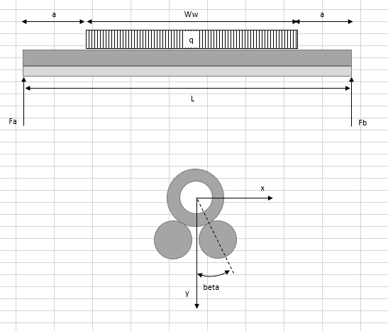
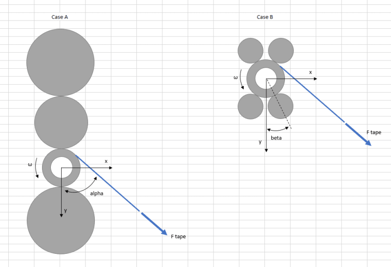
The rolls are used in a machine for winding up tape. The blue line in the figure below is the tape which comes under an angle alpha (20 - 30 degree). The tape is winded on a cardboard tube that's pushed over the steel tube. The tube rotates with a velocity ω. For winding the tape without wrinkles, the tape is pre-tentioned which results in a force "F tape" on the tube (under an angle alpha).

Currently, we use "case A" in which the tube is pre-tentioned against a lower roll and two top rolls. As the width of the tape will increase, we have to increase the length of the rolls from 2.8 meter to 3.6 meter. We want to study if the stability of the winding process is still ok and we want to compare the deflection of the rolls of case A with another known principle to support the rolls which is shown in case B. The width of the tape is smaller than the length of the rolls and therefore I have drawn a partially uniform distributed load in my original post.

It is not allowed that the tube slips between the rolls as the rolls are preloaded against the tube for pressing the tape against the cardboard tube and to overcome wrinkles during winding (beta will thus be 10 - 30 degree).
I was also thinking if I can simply add the individual I's of the system:
-In case A in can do this, i.e. adding the I of the lower roll to the I of the tube to calculate the deflection in the y-direction (not for the deflection in the x-direction). Right?
-In case B, the lower rolls are not loaded vertically. Is this still valid then?

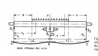
I have the formula the calculate the deflection of a beam supported at its two ends and loaded with a partially uniform distributed load.

beam_detail_qjd5em.png
 
can't you modify the machine so that to have a situation like the attached sketch (done in bending machine for steel sheets) ?

rullo_film_tzysfy.jpg


PS : in case I can post the formulas, if really needed
 
Steven C - You seem to be looking for a general formula where numbers are plugged in and an answer comes out. If you take dhengr's advice and use "real" numbers, getting a reasonable (approximate) solution should be much easier. IMHO, this type problems lends itself to an iterative solution. Make some calcs, see what the results are, make some "adjustments", and try again. It should not take long to home-in on an answer.

An example of where real numbers help: The self-weight of the steel tubes could be either a small or a large factor, we don't have a clue which it is.

[idea]
[r2d2]
 
The problem illustrated in Case B is not nearly as simple as first described.

Ftape would be a partially uniform load if the tube remains straight. If it deflects, Ftape would tend to distribute nearer the edges of the tape. The exact distribution would be dependent on the properties of the tape, tube and rolls but the revised distribution would have the effect of reducing the bending moment of the system.

Ftape is not a gravity load; it acts at an angle of alpha to the Y axis. The large tube will tend to deflect parallel to the applied force. The lower right hand roll will carry a larger share of the applied load than any of the other three rolls because of its location. The upper left hand roll will tend to lose its preload against the tube and will carry little if any of the applied load.

BA
 
I agree ... initial problem description very different from the later pix.

I'm surprised case A even works !? In case B I can see the lateral load can be reacted by the contact to the support rollers. In case A maybe the upper roller is off CL, towards the load ?

another day in paradise, or is paradise one day closer ?
 
Steven C said:
The tube rotates with a velocity ω.

There must be a motor driving the tube to rotate with a specified angular velocity in either Case A or Case B.

rb1957 said:
I'm surprised case A even works !?

The horizontal component of the tape tension is Ftape*sinα while the vertical compontent is Ftape*cosα.

In order for Case A to work, the horizontal component of Ftape must be carried by the tube alone assuming the rolls are free to rotate whereas the vertical component must be carried by the tube and lower roll. The moment about the center of tube, Ftape*r where r is the radius of the tube, is resisted by the drive motor.

BA
 
Status
Not open for further replies.

Part and Inventory Search

Sponsor