Eng-Tips is the largest engineering community on the Internet

Intelligent Work Forums for Engineering Professionals

Deflection of Simply Supported, Uniformly Loaded Beam, with Rotated Section 3

Status
Not open for further replies.

Eng16080

Structural
Jun 16, 2020
709
0
16
US
I'm working on a "simple" wood beam design tool. The beam can be rotated about it's longitudinal axis, with a rotation of 0 meaning that it's oriented in the strong direction for gravity loading, 90 degrees is a flatwise orientation, etc. The loads are always acting vertically (in the gravity direction) and for the sake of this discussion are assumed to act at the centroid/neutral axis (no torsion). The sketch below should clarify the basic conditions. I'm trying to calculate the total deflection of the beam under a uniform load for any rotation of the section. Despite scouring my resources and the internet, I can't find much guidance on this.
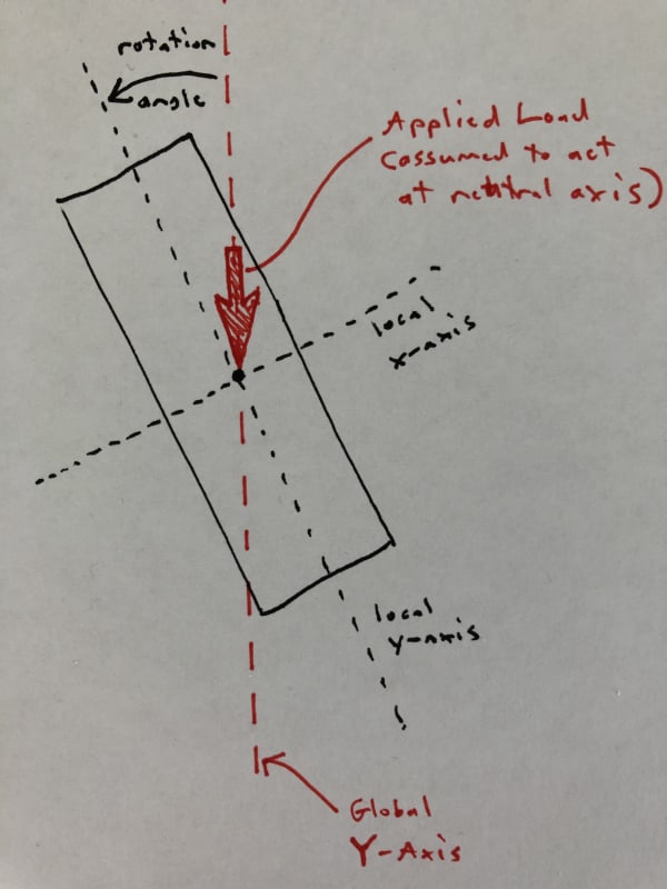
section_zhveni.jpg


With the beam oriented either vertically or flat, the calculation is simple. I use either Ix (strong axis MOI) or Iy (weak axis MOI) of the section and the equation d = 5wL^4/384EI. For the rotated section, though, I can think of 2 different ways to calculate the total deflection, which give very different results:

Method 1:
[ol A]
[li]Calculate the component of the load acting in the direction of the member's local y-axis. Then using this load (we'll call wy) and Ix, calculate the deflection, dy, which is the deflection in the direction of the member's local y-axis (strong axis).[/li]
[li]Using a similar procedure, calculate the deflection dx, in the direction of the member's local x-axis (weak axis).[/li]
[li]Calculate the total deflection: d = sqrt(dy*dy + dx*dx)[/li]
[/ol]

And Method 2:
[ol A]
[li]Given Ix and Iy, calculate I_rotated, which is the MOI with respect to the Global X-Axis, which is a horizontal line going through the centroid of the section (I should have included that in the sketch above). From my strength of materials text: I_rotated = (Ix+Iy)/2 + cos(2*angle)(Ix-Iy)/2[/li]
[li]With I_rotated calculated, calculate d from the equation above (using I_rotated in place of I).[/li]
[/ol]

I'll follow-up with a spreadsheet showing the large difference in values between the 2 methods.
 
Replies continue below

Recommended for you

How critical is the outcome? If critical, I'd be looking at using whichever was returning the most penalizing results. Wood design was never intended on being as accurate as watchmaking.
 
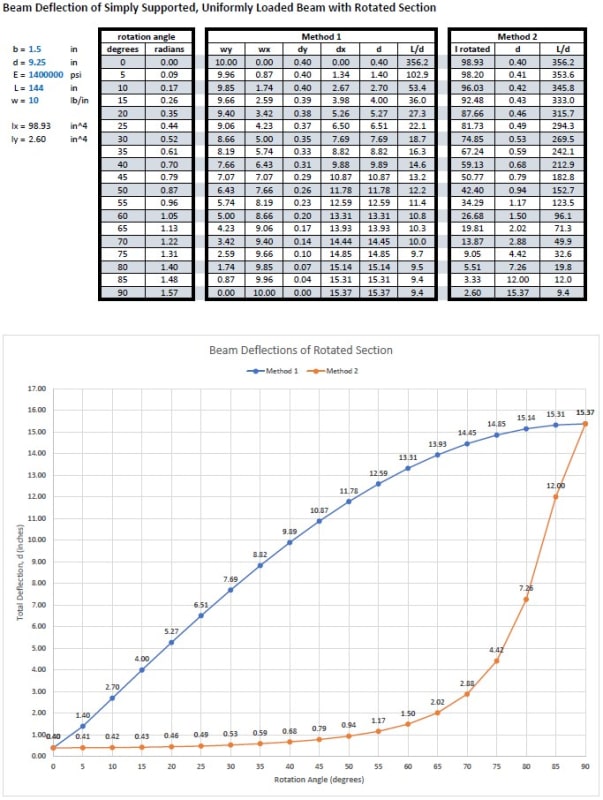
For a 2x10, simply supported, wood beam with a span of 144 in, a uniform load of 10 lbs/in, and an E of 1.4x10^6 psi, the following shows the calculated total deflection at various section rotations using both Method 1 and Method 2.
Screenshot_2024-02-08_130243_fvtejc.jpg


A few observations:
[ol 1]
[li]For rotations of 0 and 90 degrees, the results are the same for both methods.[/li]
[li]At a rotation of 45 degrees, the total deflection is 10.87" for Method 1 and 0.79" for Method 2![/li]
[li]At only a small rotation of 5 degrees, Method 1 gives a deflection nearly 1" greater than Method 2. Intuitively, this seems incorrect. [/li]
[/ol]

I initially based my analysis on Method 2, but in checking my results against Woodworks software, I was rather shocked. After some digging, it turns out that they use Method 1. I was hoping to come across some literature discussing this, but found nothing. If anybody is aware of anything or has insights into this, I'd be much appreciative! If all else fails, I might have to construct a model to test.
 
jayrod12 said:
How critical is the outcome? If critical, I'd be looking at using whichever was returning the most penalizing results. Wood design was never intended on being as accurate as watchmaking.
If all else fails, I'll definitely take the more conservative approach (which seems to be what the creators of Woodworks did). It's more that the results are so different between the 2 methods that I'm wondering if something obvious is being overlooked or I have a bad fundamental understanding of this.
 
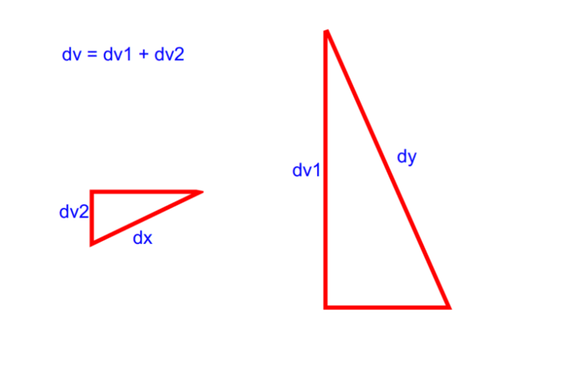
If you want the total vertical deflection, I believe equation 1C to be in error.

You need to combine the vertical component of each dy and dx.
the resultant you have calculated could be at an angle to the vertical

Screenshot_2024-02-08_131945_hubh0r.png
 
CDLD, You're right, but I was looking at the total deflection, not total vertical deflection. I may have mis-stated that above.
 
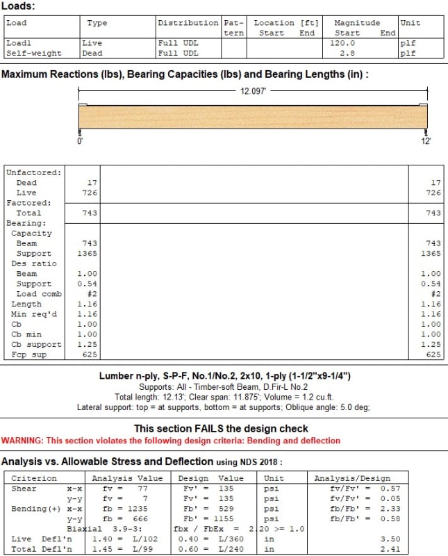
For fun, here is the output from Woodworks for the same beam that I used in my spreadsheet. The live load deflection of 1.40" is equal to the value from my spreadsheet, at a 5 degree rotation.

woodworks_output_nkmogu.jpg
 
I think method 2 is calculating the vertical deflection with respect to the global X-axis, which means that method 1 should also be calculating with respect to the global x-axis (i.e., vertical deflection)
 
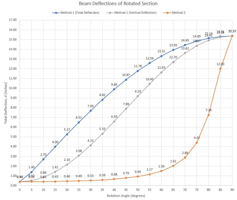
CLDL, Both are calculating total deflection in any direction, so it should be an apples to apples comparison. But you have a good point seeing that we're typically most concerned with vertical deflection. See the attached updated spreadsheet which also includes vertical deflection for Method 1.

Graph_Including_Vertical_Deflections_bnqi9d.jpg
 
CDLD,
Method 2 directly calculates the moment of inertia of the rotated section (I_rotated) with respect to the Global X axis. From there, deflection is calculated as: d = 5wL^4/384E(I_rotated).
For example, at a 45 degree angle, the 2x10 (1.5"x9.25") section has I_rotated = 50.77 in^4.
This is calculated from the equation: I_rotated = (Ix+Iy)/2 + cos(2*angle)(Ix-Iy)/2
 
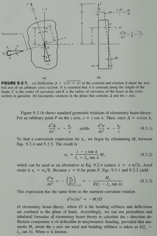
Method 2 turns into an unsymmetric bending problem and the normal d2y/dx2 = M/EI relationship no longer holds, see excerpt from Advanced Mechanics of Materials by Cook:
Screenshot_2024-02-08_142538_p1prpe.png
 
Your Method 1 resolves the loading to be parallel to the principal axis of the rectangular cross-section which restores the d2y/dx2 = M/EI relationship in each principal direction, so you can do the vector addition to determine the total deflection.
 
Ok, Method 2 is junk! Thanks for everyone's input. The three of you all had great points.

In Method 2, I calculated I_rotated with respect to the Global X-axis, which I assumed to be the neutral axis of the section. The problem is that for all rotations except 0, having the neutral axis in this location results in there being internal moments acting about the Global Y-axis due to the resultant tension and compression forces (to either side of the n.a.) not being vertically aligned. Since there are no applied moments acting in this direction, this means the section is not in equilibrium ("an unsymmetrical bending problem" as mentioned by Celt83), and therefore this is not a valid solution.

I believe I could modify Method 2 to be a valid approach by determining the neutral axis angle of the rotated section corresponding with zero moment about the Global Y-axis. Using this n.a. I_rotated would be calculated. Graphically, for a section rotated at 45 degrees, it seems like the neutral axis might be somewhere between the local y-axis and the section diagonal. It's obvious that this would result in a much lower value for I-rotated than what I erroneously calculated above, with the value probably being rather close to Iy.
 
Eng16080:

Your method 2 could work it just requires much more computation effort up front you'll need to compute Iy, Iz, and Iyz and all three components will show up in the final deflection equations. The cross-section stresses still have to obey static equilibrium and resolve to the applied moment. You may have computed stresses as just My/I, this formula is not correct for unsymmetric bending the more detailed formula, with 0 axial loading, is sigma = (-My Iyz - Mz Iy) y + (My Iz + Mz Iyz) z / Iy Iz - Iyz^2 , for any arbitrary y,z axis with origin at the cross-section centroid.

 
Celt83, for my own curiosity, I'm going to see if I can get the same result between the two methods, using the approach you described or similar. Ultimately, I'll likely just go with Method 1, as it seems much simpler.

desertfox, I (very) briefly looked at a Mohrs circle approach but I was thinking it wouldn't apply to a rectangular section because I incorrectly assumed that the product of inertia would be zero for a double symmetric section. I see now that this is incorrect. Well, rather, it's correct if the section is oriented either vertically or horizontally but not for rotated sections. Good call on that. I'll probably look at that approach as well, which it appears might be the same as the equation suggested above by Celt83.
 
Eng16080 said:
And Method 2:
Given Ix and Iy, calculate I_rotated, which is the MOI with respect to the Global X-Axis, which is a horizontal line going through the centroid of the section (I should have included that in the sketch above). From my strength of materials text: I_rotated = (Ix+Iy)/2 + cos(2*angle)(Ix-Iy)/2
With I_rotated calculated, calculate d from the equation above (using I_rotated in place of I).

In the AISC Manual (p.17-43 of the 15th ed.):
I3 (your global Ix) = Ix*sin^2(theta)+Iy*cos^2(theta).

How would that compare with your method 1 and method 2 for vertical deflection?
 
SE2607, with theta equal to 90 degrees minus the rotation angle (per my sketch), that equation gives the same value for I_rotated (which is I about the global X-axis) that I calculated. The issue with Method 2 is that I should not be using I about the global X-axis, except for a rotation of 0.
 
Status
Not open for further replies.
Back
Top