Eng-Tips is the largest engineering community on the Internet

Intelligent Work Forums for Engineering Professionals

Deflection of Simply Supported, Uniformly Loaded Beam, with Rotated Section 3

Status
Not open for further replies.

Eng16080

Structural
Jun 16, 2020
709
0
16
US
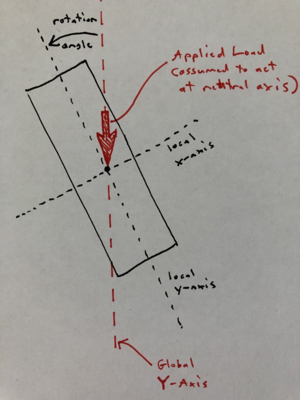
I'm working on a "simple" wood beam design tool. The beam can be rotated about it's longitudinal axis, with a rotation of 0 meaning that it's oriented in the strong direction for gravity loading, 90 degrees is a flatwise orientation, etc. The loads are always acting vertically (in the gravity direction) and for the sake of this discussion are assumed to act at the centroid/neutral axis (no torsion). The sketch below should clarify the basic conditions. I'm trying to calculate the total deflection of the beam under a uniform load for any rotation of the section. Despite scouring my resources and the internet, I can't find much guidance on this.
section_zhveni.jpg


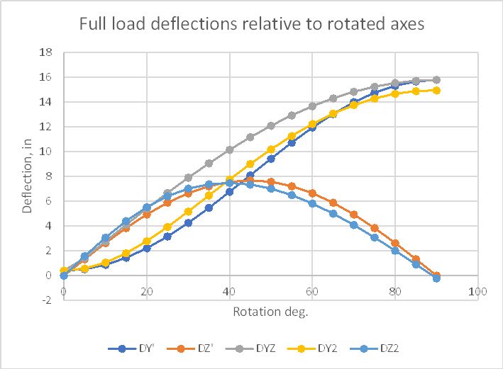
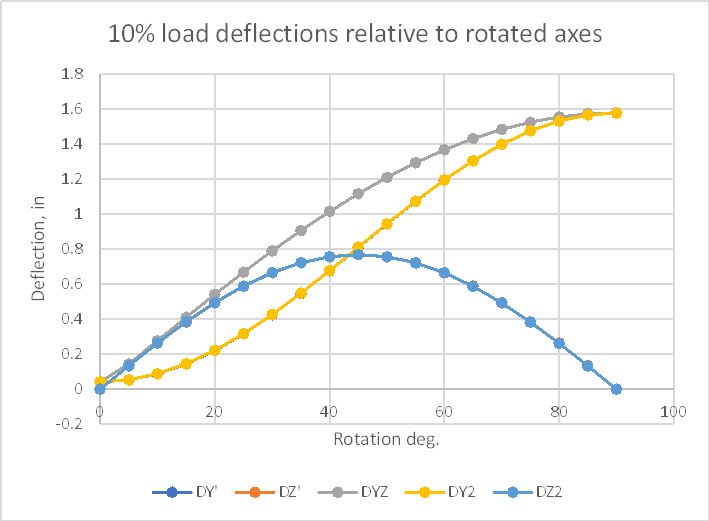
With the beam oriented either vertically or flat, the calculation is simple. I use either Ix (strong axis MOI) or Iy (weak axis MOI) of the section and the equation d = 5wL^4/384EI. For the rotated section, though, I can think of 2 different ways to calculate the total deflection, which give very different results:

Method 1:
[ol A]
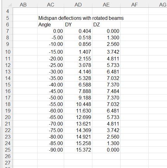
[li]Calculate the component of the load acting in the direction of the member's local y-axis. Then using this load (we'll call wy) and Ix, calculate the deflection, dy, which is the deflection in the direction of the member's local y-axis (strong axis).[/li]
[li]Using a similar procedure, calculate the deflection dx, in the direction of the member's local x-axis (weak axis).[/li]
[li]Calculate the total deflection: d = sqrt(dy*dy + dx*dx)[/li]
[/ol]

And Method 2:
[ol A]
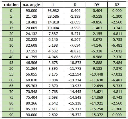
[li]Given Ix and Iy, calculate I_rotated, which is the MOI with respect to the Global X-Axis, which is a horizontal line going through the centroid of the section (I should have included that in the sketch above). From my strength of materials text: I_rotated = (Ix+Iy)/2 + cos(2*angle)(Ix-Iy)/2[/li]
[li]With I_rotated calculated, calculate d from the equation above (using I_rotated in place of I).[/li]
[/ol]

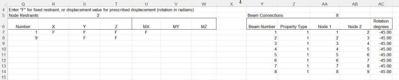
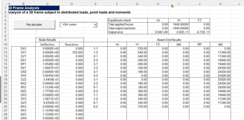
I'll follow-up with a spreadsheet showing the large difference in values between the 2 methods.
 
Replies continue below

Recommended for you

Edit: I can't read plots properly, disregard

----------------------------------------------------------------------

Why yes, I do in fact have no idea what I'm talking about
 
I'm a bit late on this, but I thought it would be interesting to check the results from a 3D frame analysis.

I have run two analyses using Strand7:
1) Loads were specified in the vertical and horizontal directions, and incrementally factored so that the resultant load rotated through 90 degrees in 5 degree increments. The resulting deflections were then rotated to find the resultant deflections parallel and perpendicular to the resultant applied load.
2) The load was applied in the vertical direction only and the beam was rotated in 5 degree increments; i.e the model replicated the actual loading as closely as possible. For this case 2nd degree geometric non-linearity was included.

The results were:
Rotated_beam1_tcohqp.jpg


... so close, but significant differences between the two runs. This waas because geometric non-linear effects were significant, and were only included in the the second run, so I reduced the load to 10% and found:
Rotated_beam2_irkv0f.jpg


... near exact agreement between the two runs.

In summary "Method 1" from the OP gives accurate results for the maximum resultant deflection, with the vertical deflection being a little lower.

Doug Jenkins
Interactive Design Services
 
IDS, Thanks for running that analysis. I would have liked to check my results against those from a frame analysis program, but don't currently have a license for one. As you mentioned, my Method 1 results appear to match your plotted results above. The "Total Deflection" and "Vertical Deflection" lines from mine look very close to the "DYZ" and "DY'/DY2" lines from yours.
 
Eng16080 - There are quite a few free options for doing 3D frame analysis, including my 3DFrame spreadsheet (attached).

It was actually pretty easy to set up this problem in the spreadsheet because you can specify a rotation angle for any beam:
Rotated_beam3_ctqqam.jpg


For each change of angle you need to recalculate the frame:
Rotated_beam4_ama0wv.jpg


Then you can extract the midspan deflections for each angle:
Rotated_beam5_kqma7y.jpg


The results are in near exact agreement with my Strand7 results where I rotated the loads, and didn't include non-linear geometric effects.

The download spreadsheet is set up with this model and the results summary table shown above.

Doug Jenkins
Interactive Design Services
 
Just for fun, can you run the graph again using a square section? I want to see what happens at 45 degree. I assume it would yield the same deflection at 45 degree?
 
IDS, Your spreadsheet looks impressive. I'll definitely take a look. I started writing a 3D Frame analysis tool awhile ago, but have yet to finish. Definitely not simple stuff. I imagine there being a lot of VBA code running behind the scenes.

DoubleStud, I believe a square shape will have the same moment of inertia no matter how it's rotated, meaning that it will deflect vertically by the same amount for any rotation (like IDS mentioned). I was a little surprised to learn this. I figured the deflection would change slightly, especially if turned 45 degrees to a diamond orientation.

For my "simple" beam analysis tool, I was hoping to not have to resort to a 3D Frame analysis to account for the member rotation (but perhaps it's inevitable). I did derive an expression for moment of inertia which seems to give total deflection (not vertical) of the beam without needing to split up the applied loads into individual components relative to the beams local x and y axes. That expression is:
I = 1 / sqrt[sin[sup]2[/sup](alpha)/Iy[sup]2[/sup] + cos[sup]2[/sup](alpha)/Ix[sup]2[/sup]]. If this leads to the total deflection (relative to the neutral axis), then if the neutral axis angle is known, the vertical deflection can be found.

I'm not fully confident this approach is correct, but it seems to work. I'll need to review mechanics of materials a bit more. It's crazy how complicated the problem becomes when the section is not perfectly vertical or horizontal.
 
Thanks IDS. Both the excel file and your website will be great resources going forward, especially if I get serious about completing a 3D frame analysis program. That looks like a ton of effort on your part.

The simple beam program that I'm currently working on uses the 2D (planar) stiffness method. While this obviously isn't as versatile as a 3D frame analysis, I figure it will cover about 95 percent of the member analysis that I typically do for a residential project (mostly wood framed). When/if I eventually create a 3D frame program, I'll also be able to use this to verify some of the results. I suppose I'm trying to create something similar to Woodworks or Forte.

Concerning the original problem I was having calculating the beam deflection, the method I described above works, at least for the example problem. I get identical results to those from your spreadsheet as well as Woodworks software:
Updated_Output_trrsu2.jpg
 
Status
Not open for further replies.
Back
Top