Continue to Site

Eng-Tips is the largest engineering community on the Internet

Intelligent Work Forums for Engineering Professionals

  • Congratulations KootK on being selected by the Eng-Tips community for having the most helpful posts in the forums last week. Way to Go!

Deflection of sistered composite wood beams

Status
Not open for further replies.

EngDM

Structural
Aug 10, 2021
388
I have come across this a few times now where an existing building is being given an addition which has a much higher roof. We plan to reinforce the existing 2x10 roof joists with LVL's as the drifting snow load is quite large. However, how does one assess the deflection accurately given that the E's are different? They are sistered side by side, would it be as simple as finding the weighted EsI for the combined shape?

In the past I have just sized the new reinforcing to take the entire deflection, which is way over-designed if deflection is what governs in my opinion, but it is quick.
 
Replies continue below

Recommended for you

If they are truly bound together to have equal displacement then you can solve this by determining what the proportion of load carried by either member is then solving that member under those loads for deflection. You should find that following the same approach on the other member gives equal deflection otherwise something has gone wrong.

Curious what proportion of the load you have assigned to each member, or just all to the LVLs?
 
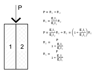
As driftlimiter said, if they're setup correctly, then they take a portion of the load proportional to the stiffness of each component.
1_e8lj5w.png

I usually just figure out the percentage of the total load that goes to each component and then analyze each as separate beams. The resulting deflection for each will be equal.

For framing, usually the load is applied to the tops of each component, which does not necessarily make it a composite beam. It's just two separate beams that take a portion of the total load. In other cases, you need to analyze it as a composite beam and make sure the components are attached adequately.
 
The LVL will be alot stiffer than the existing joist so be aware of that, I have gotten away with completely ignoring the existing member for strength, then finding that the new lvl can carry all the load and meet deflection requirements alone. Might be the simplest approach but can work in certain situations.
 
For two wood beams, I would keep it simple and just add up EI beam1 and EI beam2 and run the deflection calc with a combined EI. The different stiffness is accounted for by the different E's.
 
I wouldn't say alot, a 1.75 x 9.25 LVL (2.0E) is only 46% stiffer than a 2x10 (1.6E).
 
Yea I suppose your right kissymoose, even with that extra 42% stiffness I'm getting that it only carries around 20% more load

I will have to go back and see what I was thinking about.

I think I had a case where I needed two LVL sisters and it just ended up being simpler to ignore the existing member.

 
driftLimiter said:
I'm getting that it only carries around 20% more load
Well that's interesting, it should be carrying 42 46% more load if it's 46% stiffer. How'd you get to 20?
 
I set EI of the 2x10 to 1 and EI of the lvl to 1.46.

2x10 factor is 1 / (1 + 1.46) = 0.407
Lvl factor is 1.46 / (1 + 1.46) = 0.593

Difference = ~ 0.6 - 0.4 = 0.2

I did do this totally back of the napkin. Normally I would just calculate midspan deflection of either beam under a unit load and use K = 1/delta for this weighted average.
 
Got it, thanks for sharing.
It takes 20% more of the total load, 46% more than the load of the 2x10.
 
Could this not be treated as a flitch beam analysis and thus tackle the problem using transformation of section properties? In this case, start your calculations with calculating the n value, n = E_LVL⁄E_wood (depending on which way you transform).
 
kissymoose said:
As driftlimiter said, if they're setup correctly, then they take a portion of the load proportional to the stiffness of each component.

In the case where the sistered member is larger in depth, and the tops are flush, is the Ix of both joists calculated from their respective neutral axis', or rather from the neutral axis of the combined shape?
 
Going off on a tangent here but I think it's worth pointing this out.

GaryHStr said:
It's important to accurately assess the deflection of the existing roof joists when considering reinforcing them with LVLs. While sistering the joists can help to increase their capacity, the difference in E values can make it difficult to accurately predict deflection.

One approach could be to use the weighted EsI for the combined shape, as you suggested. However, this may not provide a completely accurate assessment, as other factors such as the stiffness of the connections between the existing joists and the new LVLs should also be considered.

To more accurately assess deflection, you could consider using a structural analysis software or consulting with a structural engineer. This would allow for a more detailed analysis of the structure, taking into account factors such as the loading conditions, boundary conditions, and material properties.

While overdesigning may be a quick solution, it may result in unnecessary costs and could potentially lead to other issues down the line. It's important to ensure that the reinforcing is appropriately sized and that deflection is within acceptable limits to ensure the safety and functionality of the structure.

Is it just me or does this sound like ChatGPT...? Out of curiosity I copied OP's top level post into ChatGPT and here is it's response:

ChatGPT said:
Assessing the deflection accurately in this case can be more complicated due to the difference in modulus of elasticity between the 2x10 roof joists and the LVLs. As you have mentioned, one way to estimate the deflection of the combined section is to find the weighted EsI for the combined shape. However, this approach assumes that the deflection of the two materials is similar, which may not be the case due to their different modulus of elasticity.

A more accurate approach would be to model the entire roof system using finite element analysis software. This approach would allow you to model the entire system including the roof joists, LVLs, and any other components such as the roof sheathing and insulation. By doing this, you can accurately model the behavior of the system under different load cases and assess the deflection and stress distribution throughout the structure.

If you choose to use this approach, it would be a good idea to consult with a structural engineer or other qualified professional who is experienced in using finite element analysis software. They can help you to develop an accurate model and ensure that the results are reliable.

Regardless of which approach you use, it is important to ensure that the deflection of the roof system is within acceptable limits to avoid damage or failure of the structure. Building codes and industry standards often provide guidance on acceptable deflection limits for different types of structures, so it may be a good idea to consult with these resources as well.

We are entering a new era of the internet, folks.

I'm not intending to do any witch-hunting here but Gary's replies to other threads are eerily similar and vague. Note that if you experiment with this you will get a slightly different response each time you ask it (ChatGPT) a question.
 
I agree the response seems to lack context of other replies in the thread and the OP. Looking over the other replies from this user there is a consistent style for sure.
 
I'm impressed you thought to check chatGPT. I do find it interesting how Gary's replies seem to follow the same formal format and recommends consulting a structural engineer. He doesn't say another structural engineer, or a subject matter expert, as if he's not aware that he is most likely addressing a structural engineer. This is quite interesting. I'd hate to be bullying someone on the internet for how they communicate, but I think you're onto something dold.

Also, EngDM, please feel free to direct us back to your questions. I'm sorry the thread has taken on a few tangents, though I'd like to think the first was helpful in its relevance.
 
dold said:
Is it just me or does this sound like ChatGPT...? Out of curiosity I copied OP's top level post into ChatGPT and here is it's response:
I agree 100%. I am a structural EIT in Canada, and have the structural notaion beside my username. When he wrote to consult a structural engineer needless to say I was a bit confused.

kissymoose said:
Also, EngDM, please feel free to direct us back to your questions. I'm sorry the thread has taken on a few tangents, though I'd like to think the first was helpful in its relevance.

Your first reply was very helpful. I was able to run the numbers and get my deflection to match in this fashion.

I tried doing the same by getting an E*I from sectionproperties's library functions, but the delfection I calculate with this combined E*I is way off deflection wise when I use it. Curious as to why this is.
 
EngDM said:
I tried doing the same by getting an E*I from sectionproperties's library functions, but the delfection I calculate with this combined E*I is way off deflection wise when I use it. Curious as to why this is.
1_x6bs0v.png

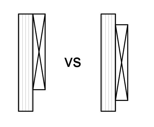
I'm gonna guess you analyzed it like the left condition, but we're talking about it behaving like the right condition, despite it likely being constructed to look like the left. On the right, both members bend about their individual centroids, where for each member, the top compressive stress is equal in magnitude to the bottom tensile stress. To behave like a single, composite member as shown on the left, the members would have to be fastened together to behave as one, where the strain at any point is the same for each. The composite member will have an increased I, smaller deflection, and put more flexural stress in the bigger member than the condition on the right.
 
kissymoose said:
I'm gonna guess you analyzed it like the left condition, but we're talking about it behaving like the right condition, despite it likely being constructed to look like the left. On the right, both members bend about their individual centroids, where for each member, the top compressive stress is equal in magnitude to the bottom tensile stress. To behave like a single, composite member as shown on the left, the members would have to be fastened together to behave as one, where the strain at any point is the same for each. The composite member will have an increased I, smaller deflection, and put more flexural stress in the bigger member than the condition on the right.

In my specific example that I tried the combined E*I, the depth of the members were the same (2x10 sistered with 9/14" LVL) so the centroid would be the same for both, and they would still be acting individually about their own axis. I'm just curious as to why it doesn't compute the same as doing the force splitting method in your screenshot in reply #2.
 
Status
Not open for further replies.

Part and Inventory Search

Sponsor