Continue to Site

Eng-Tips is the largest engineering community on the Internet

Intelligent Work Forums for Engineering Professionals

  • Congratulations GregLocock on being selected by the Eng-Tips community for having the most helpful posts in the forums last week. Way to Go!

Deflection of unbonded multiple steel plates 1

Aldsap

Structural
Dec 24, 2024
1
How do you calculate the deflection of three unbonded layers of steel plates with a middle point load ?
 
Replies continue below

Recommended for you

Assuming weightless plates of zero depth and a true point load, the top two plates will curve upwards at the point of contact and lift off the plate below. All the load will therefore transfer to the lower plate at the load position, which will deflect exactly the same as if the top two plates were not there.

For real plates with real loads it gets a little more complicated of course, but the full deflection of the bottom plate alone is a reasonable conservative assumption.

For a discussion of what happens with a UDL see:
 
If you could sketch you setup perhaps a leaf spring designer would help you out. An experiment with 3 steel rules might be instructive.
 
On reflection my previous post was a little over-conservative.

The bottom plate will deflect downwards until the upper plates have the same curvature and are in contact over the full length, so the load will be distributed between all the plates in the stack.
 
I spent some time thinking over your idea too. If the upper layers are unbonded and unrestrained, then the lower layer is going to dominate the solution, maybe closer to a single layer with a distributed load. How much energy is absorbed by the other plies ? Humm, but then the upper plies, initially straight (undeflected), would need to conform to the lower one, pushed there by the applied load and the underlying layer. What does the deflected shape of 1 layer where the load is reacted by a distributed load compare to a single layer loaded by the same distributed load, reacted at the supports ? Would the upper layers lift off the lower layer ?? It seems to me that the upper layer might deflect with a tangent (into their unloaded span) but the lower layer would always hit this tangent.
 
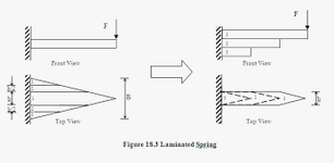
IDS, you were on the right track, the ends of the first two layers do little initially. If you look at a leaf spring the geometry may seem odd, but the bending stiffness is not far off that of a trapezoidal or triangular plate made of the three leaves lying side by side. Crucially the length will change as the beam flexes, that is why we have hangers on leaf springs. Extending the length of the lower leaves does affect the rate, in a non linear fashion, to give a rising rate.

1735161457591.png
 
Last edited:
Things do get complicated when some of the beams do not extend full length, as in Greg's example and the discussion at:

But for two or more stacked beams or plates spanning between the supports, with a point load at mid-span, it is quite simple. If the central point load is distributed between the plates equally then they will all deflect the same distance with the same curvature at any section over the full length. They will therefore be touching with no stress transfer at the interfaces, except at mid-span and the supports. That arrangement will be in force and geometric equilibrium, so that is what happens.

For real plates that are not perfectly uniform along the length no doubt there will be some small stress transfer at points along the length, but that wouldn't make a significant difference to the overall behaviour.
 
two stacked plates, unbonded, point load mid span ... wouldn't the upper plate see (as a FBD) the applied point load and a distributed reaction (loading the 2nd plate) and the 2nd plate would see the two point reactions and the distributed load. These two situations don't seem to be obviously equivalent, ie the same deflected shape, but that may be what defines the distributed loading between the plates.
 
@rb1957 - but if there is a distributed loading between the plates, they will have a different shear force distribution, so they will have different curvatures, so they can't be in contact other than at points, so there can't be a distributed loading.

A simple thought experiment that convinced me the point load would be distributed equally between all three beams at the load location was to imagine the load applied as separate equal loads to each of the beams. Clearly they will all deflect the same amount, so stay in contact but with no distributed interaction force. Now imagine the loads are removed from the two lower beams, and equal loads are simultaneously applied to the top beam. The beams would stay in the same load condition, and so would not move.
 
We have to assume the plates are all the same length, no friction as it has not been stated otherwise. Isn't this a first year mechanics of materials question?
It will be one third the deflection of one plate.
That is what I would assume.
 
The devil is in the loading from zero, once all the plates are firmly in contact then the 1/3 calculation is correct.
 
The devil is in the loading from zero, once all the plates are firmly in contact then the 1/3 calculation is correct.

Which in the case of structural applications is almost always a safe assumption at limit load of serviceability and strength.

We structural engineers deal mostly with "simple" behaviour. You clever Automotive/Mechanical engineer often face more complex behaviour and it is often by a deliberate design choice as non linear serviceability behaviour can often be quite desirable.

As XR250 said:

Isn't this a first year mechanics of materials question?

But as we know even the simplest questions on Eng-Tips can sometimes evolve.
 

Part and Inventory Search

Sponsor