Tek-Tips is the largest IT community on the Internet today!

Members share and learn making Tek-Tips Forums the best source of peer-reviewed technical information on the Internet!

  • Congratulations cowski on being selected by the Eng-Tips community for having the most helpful posts in the forums last week. Way to Go!

Deflection time history

Status
Not open for further replies.

Hussain2339

Civil/Environmental
Joined
Jun 4, 2021
Messages
59
Location
AU
Dear all

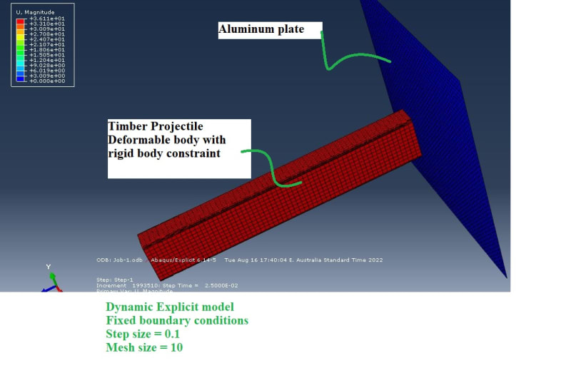
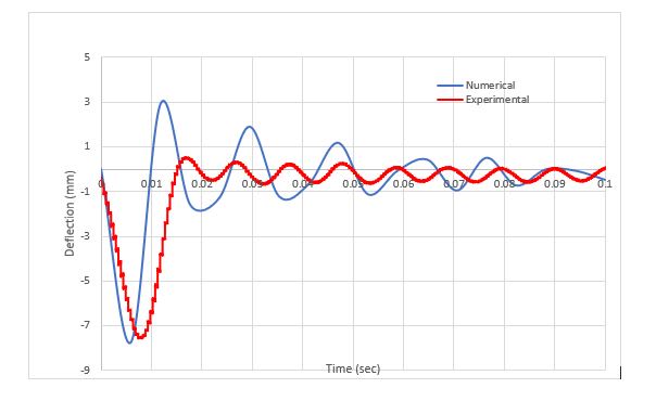
I am doing timber impact on the aluminum plates. My numerical and experimental curves have some lag.

Can you please advise, on how can I improve the model?

Picture is attached

88899_k3pbsj.jpg
 
It's hard to say without knowing any details about the model. Can you share some information regarding the step type, boundary conditions, loads, material models and so on ? Screenshots would be useful as well.
 
Load is applied as velocity to the reference point of projectile
Pice-wise linear plasticity model (Elasto plastic model)
For rest info please see the photo attached
Capture_weul27.jpg
 
The plate is fixed on the edges, right ? Does it represent the supports used in the experimental setup well ? Is the projectile fully rigid ?
 
The plate is fixed on the edge,and it represents the same support condition as in the experiment

The projectile is a deformable body with rigid body constraint
 
All right but is the rigid body constraint applied to the whole projectile or just its back face, for instance ? If it's applied to the whole projectile, maybe you could try with a deformable projectile to see if this helps.
 
Status
Not open for further replies.

Part and Inventory Search

Sponsor

Back
Top