Hi everyone,
First post here, so let me know if anything in this post is not as it should be.
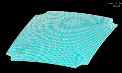
I am currently analyzing a thin-shell structure using ANSYS with 2 layers of SOLSH190 (solid-shell) elements as shown below. The thin-shell has the four circular corners that are fully fixed, and is subjected to uniform loading (applied at each top node). The analysis is geometrically nonlinear. I performed a convergence study and benchmarked the model against another model with shell (SHELL181) elements, so I am fairly confident in my results.

Since I have 2 layers of elements, that makes 3 nodes through the thickness. I am trying to back-calculate the stresses in the middle node from the stresses in the top and bottom nodes, but I am struggling to do so. I assumed that the middle node stresses would be equal to the average of the top and bottom stresses but that is not the case.
Is there something I am missing here, or am I wrong in thinking that I can back-calculate the stresses in the middle node ?
Thanks for the help
First post here, so let me know if anything in this post is not as it should be.
I am currently analyzing a thin-shell structure using ANSYS with 2 layers of SOLSH190 (solid-shell) elements as shown below. The thin-shell has the four circular corners that are fully fixed, and is subjected to uniform loading (applied at each top node). The analysis is geometrically nonlinear. I performed a convergence study and benchmarked the model against another model with shell (SHELL181) elements, so I am fairly confident in my results.

Since I have 2 layers of elements, that makes 3 nodes through the thickness. I am trying to back-calculate the stresses in the middle node from the stresses in the top and bottom nodes, but I am struggling to do so. I assumed that the middle node stresses would be equal to the average of the top and bottom stresses but that is not the case.
Is there something I am missing here, or am I wrong in thinking that I can back-calculate the stresses in the middle node ?
Thanks for the help
