Hi guys,
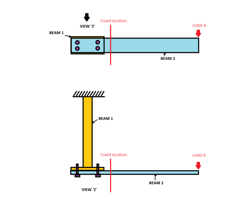
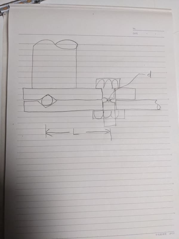
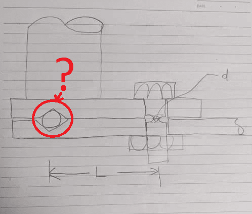
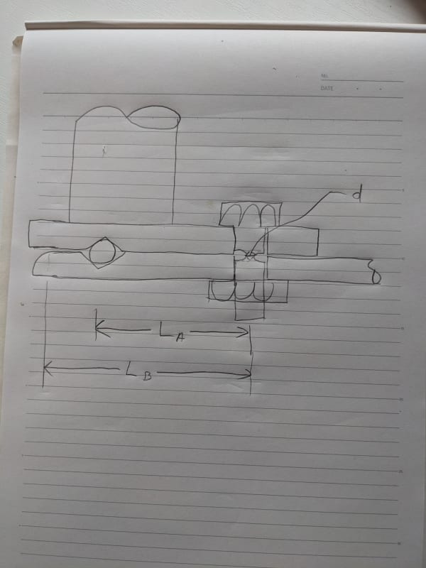
I am currently working on a development project and I am looking for some ideas for a "fused" solution, see attached image.

In simple theoretical form, the design utilizes 2 beams that are attached together, see attached image.
Beam 1 is fixed on one end. beam 2 is fixed to beam 1, the method of attachment is currently TBD depending on the fuse solution.
2 different overload cases are considered, namely:
Load A acting in the vertical direction at the most outer edge of beam 2.
Load B acting horizontally, again at the most outer edge of beam 2.
The 2 loads ae acting independently and separately (i.e. not simultaneously)
The requirement is to design a "fused" solution that prevents the overloading on beam 2 (load A or B) from being reacted by Beam 1. This will be accomplished by demonstrating that the margin of safety is the lowest at the fused location, so that when X load is applied in the directions of Load A or B, beam 2 should fully detach at the fused location, and not just yield/bend (and this is the challenge).
The single fuse point should work for both load cases and should be as close to the beam1-beam2 attachment a possible.
Any ideas?
I am currently working on a development project and I am looking for some ideas for a "fused" solution, see attached image.

In simple theoretical form, the design utilizes 2 beams that are attached together, see attached image.
Beam 1 is fixed on one end. beam 2 is fixed to beam 1, the method of attachment is currently TBD depending on the fuse solution.
2 different overload cases are considered, namely:
Load A acting in the vertical direction at the most outer edge of beam 2.
Load B acting horizontally, again at the most outer edge of beam 2.
The 2 loads ae acting independently and separately (i.e. not simultaneously)
The requirement is to design a "fused" solution that prevents the overloading on beam 2 (load A or B) from being reacted by Beam 1. This will be accomplished by demonstrating that the margin of safety is the lowest at the fused location, so that when X load is applied in the directions of Load A or B, beam 2 should fully detach at the fused location, and not just yield/bend (and this is the challenge).
The single fuse point should work for both load cases and should be as close to the beam1-beam2 attachment a possible.
Any ideas?


