Blackstar123
Civil/Environmental
- May 5, 2013
- 253
BACKGROUND INFO
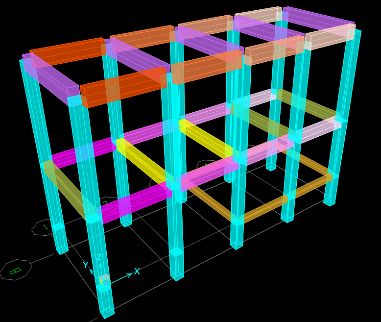
I am checking the design of an existing G+1 building with a total plan dimension of 25m (L), 9m (W) and a height of 14.8m, as shown in following fig.
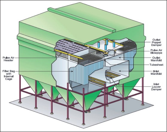
There is a standard live load of 100 psf on first floor and, equipment loads (provided by supplier) at roof level. The height of this equipment is almost 13 m and is similar to as shown in the following fig.
The structure of the building is supposed to be IMF moment frame subjected to Zone 2B earthquake loads. The design check of the structure shows that beam column capacities are adequate but structure shows a “strong beam and weak column” behavior. Thus, columns and joints are proposed to be retrofitted using FRP by specialized consultants. I am responsible to provide them the required column and joint capacities for FRP design.
QUESTON
I am using the following methodology to achieve this goal. I’ll be thankful if someone could confirm if what I am doing is right or if I am way off my rockers.
I am using sap2000 to perform a push over analysis and a sort of performance-based design. I am not going too deep into performance-based design because my understanding is very limited. My goal is to find the load at which beams will go into plastic region before the columns.
For push over analysis, I first loaded the structure with D + 0.5L + 1Equip. and then incrementally pushed the frame upto 0.02h. I’ve assigned auto generated plastic hinges as per FEMA-356 to frame members, “M3 hinge” at beam ends and “P-M2-M3 hinge” at column ends. Although I’ve a good theoretical understanding how a M3 hinge behaves. I cannot say the same about P-M2-M3 hinges. I’ll be obliged if someone could provide me with a good reference on the subject matter or can explain the behavior in detail.
Also to provide some of the facts, while modelling this nonlinear behavior,
1. I’ve not taken into consideration the extra rotation due to (i) Cracking at negative moment region and (ii) Shear cracks. At this level, I consider this a conservative assumption for column and its joints, because the more load a beam can take, the higher the design load will be obtained for column design from analysis. I am aware that this might not be the most economical option for client.
2. I’ve considered the true stress-strain curve of the rebar and not the conventional perfectly plastic model because I believe the rebar will be in strain hardening regime at higher EQ loads.
3. I’ve also considered cracked property modifiers for frame sections (0.5 for beams and 0.7 for columns).
I’ll report the forces in column for FRP design at that “step” in which rotation in beams reached the “Life safety” range as per FEMA. These forces will not be increased using a load factor. I’ll be thankful if someone could confirm if what I am doing is right or could suggest a better way to find the design load.
I am checking the design of an existing G+1 building with a total plan dimension of 25m (L), 9m (W) and a height of 14.8m, as shown in following fig.
There is a standard live load of 100 psf on first floor and, equipment loads (provided by supplier) at roof level. The height of this equipment is almost 13 m and is similar to as shown in the following fig.
The structure of the building is supposed to be IMF moment frame subjected to Zone 2B earthquake loads. The design check of the structure shows that beam column capacities are adequate but structure shows a “strong beam and weak column” behavior. Thus, columns and joints are proposed to be retrofitted using FRP by specialized consultants. I am responsible to provide them the required column and joint capacities for FRP design.
QUESTON
I am using the following methodology to achieve this goal. I’ll be thankful if someone could confirm if what I am doing is right or if I am way off my rockers.
I am using sap2000 to perform a push over analysis and a sort of performance-based design. I am not going too deep into performance-based design because my understanding is very limited. My goal is to find the load at which beams will go into plastic region before the columns.
For push over analysis, I first loaded the structure with D + 0.5L + 1Equip. and then incrementally pushed the frame upto 0.02h. I’ve assigned auto generated plastic hinges as per FEMA-356 to frame members, “M3 hinge” at beam ends and “P-M2-M3 hinge” at column ends. Although I’ve a good theoretical understanding how a M3 hinge behaves. I cannot say the same about P-M2-M3 hinges. I’ll be obliged if someone could provide me with a good reference on the subject matter or can explain the behavior in detail.
Also to provide some of the facts, while modelling this nonlinear behavior,
1. I’ve not taken into consideration the extra rotation due to (i) Cracking at negative moment region and (ii) Shear cracks. At this level, I consider this a conservative assumption for column and its joints, because the more load a beam can take, the higher the design load will be obtained for column design from analysis. I am aware that this might not be the most economical option for client.
2. I’ve considered the true stress-strain curve of the rebar and not the conventional perfectly plastic model because I believe the rebar will be in strain hardening regime at higher EQ loads.
3. I’ve also considered cracked property modifiers for frame sections (0.5 for beams and 0.7 for columns).
I’ll report the forces in column for FRP design at that “step” in which rotation in beams reached the “Life safety” range as per FEMA. These forces will not be increased using a load factor. I’ll be thankful if someone could confirm if what I am doing is right or could suggest a better way to find the design load.