Continue to Site

Eng-Tips is the largest engineering community on the Internet

Intelligent Work Forums for Engineering Professionals

  • Congratulations SSS148 on being selected by the Eng-Tips community for having the most helpful posts in the forums last week. Way to Go!

Design of a Embedded Steel Pile. Unbraced length and LTB modification factor, Cb

Status
Not open for further replies.

structuralAutoMatt

Structural
Mar 28, 2022
6
I am designing a steel embedded pile, I am in charge of the pile design given vendor supplied loading at the top of pile. The top of pile loading consists of a shear, axial, and negative moment, as shown in the attached sketch. Currently I am using the unbraced length of the pile to be 12" below grade, using LPile to get the design moment as this location, and checking the unbraced portion of the pile for LTB, flange buckling and combine force per AISC 360, chapter H.
1) This 12" is an assumption is there a better way to calculate the location of this point?
2) The maximum moment occurs below this point, I am assuming the pile is fully braced below this point, so am only checking plastic bending at this for this maximum moment demand. For these checks I am using the effective length method with K = 2.1, assuming the pile top is free to rotate and translate. My question is that if a negative moment is being transferred to the top of pile is this assumption correct, can I instead use a K = 1.2? Does this depend more on the geometry of the connection or is knowing that that connection transfer this negative moment into the pile enough to say that the pile is free to translate but not rotate? In LPile the output gives me a curvature of -0.00002 rad/in at the top of pile. A curvature of 0 represents a fixed connection, correct?
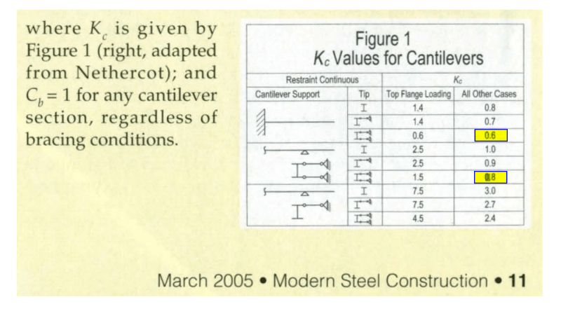
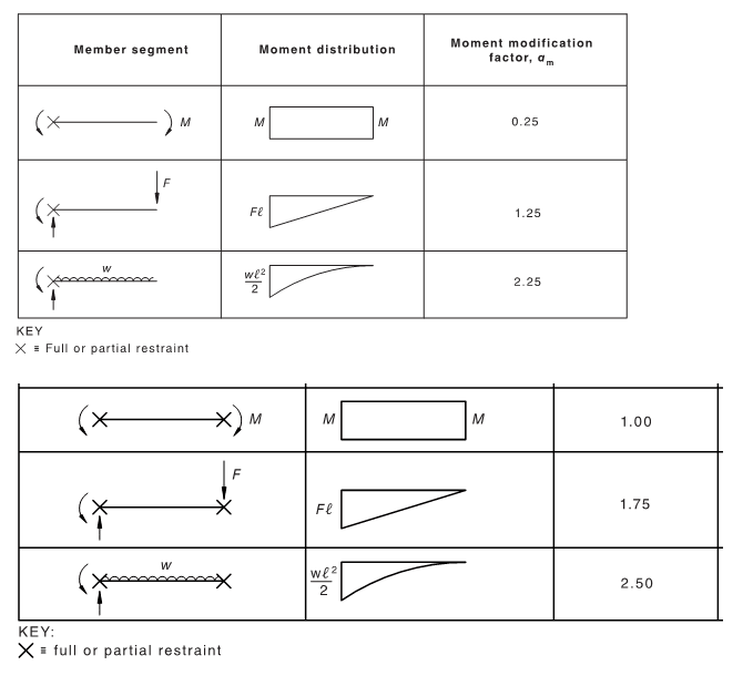
3) The next question is that is, should Cb = 1.0? or since the a moment is transferred into the pile can I assume it is braced and calculate Cb per F1-1?

Thanks in advance.

[URL unfurl="true"]https://res.cloudinary.com/engineering-com/image/upload/v1648491055/tips/EmbeddedPileSketch_lxhha7.pdf[/url]
 
Replies continue below

Recommended for you


What about the pile cap ? How the loads transferred to pile top ? K value will vary acc to if the pile top is free to rotate or fixed ..
 
The pile has vertical slotted holes and the pile cap has horizontal slotted holes and is bolted into each flange with two bolts in a vertical line. This would suggest that the pile head is free to translate and rotate but if a force couple that produces the negative moment is directly proportional to the amount of shear acting at the top of pile and this negative moment keeps the curvature at the top of pile less than or equal to zero then can it be assumed as fixed against rotation, free to translate? Also does this mean Cb can be take as something greater than 1.0?
 
1) You can estimate effective point of restraint from the output but it's still judgment. Some use the maximum moment location, some use where the moment returns to zero. It used to be common to take it as 3~4*diameter for dense/stiff ground and 8~10* diameter for loose/soft as a guide, for axial load. I'd take the same for bending for simplicity.

2) K depends on the stiffness of the restraining element at the pile head. If it's transferring moment, it must provide some restraint but K=1.2 might be optimistic. I didn't understand your description of the connection.

3) Bracing for LTB depends on restraining the twist of the section. Again, depends on exactly what the pile is connected to.
 
Thank you for your response. It is a solar tracker similar to the one pictured at the top of the linked article (Link), in the picture you can see that the holes in the pile are vertically slotted, but you may not be able to see in the photo that the holes in the pile cap are slotted horizontally.

In item 2 you say that K depends on the stiffness of the restraining element at the pile head, this distinction does not need to be made in the LTB bracing, correct? As long as there is some restraint against twisting, which, as you say, there must be to transfer moment then the end is not free, therefore Cb>1.0?


Out of curiosity, I must ask: why do you design against LTB? The soil supports the pile from all sides (while the reaction is idealized to act from two possible directions, perpendicular to the beam longitudinal axis), and the only buckling mode that a reasonably sized section can have is a flexural mode. I have never heard of anyone designing a pile (embedded in soil and connected to a pile cap) against LTB. It will definitely take more energy for the pile to buckle laterally-torsionally than it will require to make it buckle flexurally. The primary buckling-inducing load for fully (or almost fully) embedded piles is not the moment, but rather the axial compression (M << Mcr for a reasonable choice of cross-section, but not necessarily N << Ncr).

Pile buckling is a minor issue most of the time; unless the soil is cohesive with a very low shear strength, the modulus of subgrade reaction will be large enough to almost always guarantee that pile geotechnical capacity is the limiting factor, and not the buckling strength or axial compressive capacity. In your shoes, I would focus more on bending, shear, soil pressure (it may not exceed the maximum pressure that can be mobilized) and geotechnical bearing capacity than I would on buckling. Of course, a local code prescription may invalidate everything I´ve written in this post.

PS. If you want to account for the bending-compression interaction properly (i.e., not make do with an eigenvalue analysis or a "quasi-nonlinear" simplified method where the eigenvalue buckling load appears in a knockdown factor), you must perform general materially nonlinear (moment-curvature for concrete) and geometrically nonlinear (governing equations written for combined axial and transverse loads, load applied in steps and the load-deflection curve solved iteratively for each load level with e.g., Newton-Raphson) analysis. The LTB calculation is an eigenvalue analysis, just as a flexural buckling calculation, and thus does not add much "accuracy" to the buckling prediction.
 
Is yours taller, or the sketch wasn't to scale? That one look less than three feet out of the ground.

Anyway, that connection doesn't look as though it restrains much, and I assume that black strut isn't a brace given the way you're analysing it. So I'd say unrestrained at the top, and guess that your low curvature from analysis means low moment rather than restrained. Restrained/free head is an input in LPile IIRC, not an output. That example you provided looks as though it's sized for deflection.

Centondollar, the buckling check is for the bit that's out of the ground. How long would it take you to analyse using the rigorous method including soil non-linearity and what software do you use? Would you do sensitivity checks given the soil stiffness is usually a rough guess?
 
@centondollar: I am checking the portion of pile that is out of the ground for LTB, from the top of pile to 12" below grade. The pile in the photo is very short, but it is normal for these W6 piles to stick a max of 5'-6' out of the ground. LTB does govern design some of the time using a KL = 2.1*84" = 176.4".

@steveh49: The black strut is a hydraulic cylinder that helps dampen and introduce that negative moment in high winds, in high winds the panels go into the stowed position, so the higher the shear then the more load the strut takes then the higher the negative moment, which keeps the curvature at the top of pile less than 0 rad/in. This is why I would like to use K=1.2 and Cb=1.67.

In addition to checking the combined forces per AISC 360 Chap H for the portion of the pile out of the ground, I am using the free head in LPile as an input and also running LPile's buckling analysis which calculates the deflection at given shear and moment, for various axial loads and gives a buckling load for which the lateral deflection increases without limit. KL is not an input into this analysis, but this analysis does consider the non-linear soil response. It is my understanding that this is a sperate check than what is in AISC 360 chap H, and those checks still need to be run in a separate analysis, in which KL is an input.


structuralAutoMatt ;

The assumption of embedded portion would be pile behavior is not reasonable.. In order to modelling with soil springs and analysis with LPILE or so, the embedded length should be at least several meters. In your case, the embedded portion could be 1.0-1.5 meters and so, pier foundation , pole foundation assumption is reasonable.

Pls look to the past threads .. one of them ;


thread507-492495


Discard what I wrote earlier. HTURKAK is right: a 12 inch embedment does not make it a pile at all, but rather a flagpole (cantilever) for which the soil should not be modelled and instead a proper foundation block (anchor block of reinforced concrete) should be constructed at the tip of the "pile". I did not notice the unit (12'' is not common terminology where I live) when I wrote my first post.

PS. If you do non-linear analysis, a separate check for buckling using eigenvalue procedures should not be required, because non-linear analysis captures buckling at a lower load than the eigenvalue load and is thus conservative.

@steveh49: I would do sensitivity checks, yes, because the soil spring stiffness is not an accurate and readily available parameter. The calculation may be done in any software that allows nonlinear modelling; I am not sure if LPILE actually performs non-linear analysis (as in iteratively solving the geometrically and materially nonlinear bending problem), or if it just performs linear solutions successively and updates the modulus of subgrade reaction until the generated soil-pile interface pressure is acceptable. Last time I checked, it analyses P-delta effects by the simplified method instead of performing a nonlinear calculation procedure.
 
Sorry for the confusion, the pile is not embedded 12", 12" below grade is what I am assuming as the point in which the pile is continuous braced by the soil, see the sketch in the original post. So my Lb = pile projection + 12", for example for a 5' pile projection the effective length, KL, is (60"+12")*2.1=151.2" this effective length is used to check the pile as a beam-column for the unbraced portion above grade. The embedment must be much deeper than this, you are correct that 1-1.5m is typical. I have a good grasp on this analysis. My questions are:
1) What is a more accurate method in calculating the unbraced length of the pile? I have a feeling that the assuming that the pile is braced 12" below grade is conservative. I am willing to do a more in depth analysis to get a more accurate value here. What analysis is required to prove at what point below grade the pile is braced?
2) If a fixed connection is defined as a connection in which the angle between the two connecting elements do change under the loading conditions, then this top of pile connection meets that definition. Can the top of pile be considered as fixed against rotation because the curvature at the top of pile is always less than or equal to zero under all loading conditions?
3) Given the loads we know that a moment is being transferred to the top of pile in order for this to happen the connection must have a certain stiffness, is this alone enough to confirm that the pile is braced against twisting, so Cb>1.0? If not, what check is necessary to prove that the pile cap provide enough stiffness so that the pile will not rotate about it's longitudinal axis?
 
Fascinating problem. In everything that follows, I've made the following assumption:

1) With respect to buckling, we're talking about lateral torsional buckling (LTB) and only LTB.

2) The following are true of your setup:

a) The top rail cannot move laterally, along its longitudinal axis, without dragging the pile tops along with it.

b) The tops of the piles cannot rotate about their longitudinal axes without engaging the top rail in bending.

OP said:
1) What is a more accurate method in calculating the unbraced length of the pile? I have a feeling that the assuming that the pile is braced 12" below grade is conservative. I am willing to do a more in depth analysis to get a more accurate value here. What analysis is required to prove at what point below grade the pile is braced?

I don't know that 12" is excessively conservative. Moreover, I'd be pretty surprised if anybody knows of a way to accurately asses the depth at which the pile is properly restrained against LTB. LTB restraint in this situation needs to be cross section rotational restraint, not just lateral restraint. I don't believe that L-Pile, or the methods that it employees, speaks to this in any meaningful way. As far as I know, steveh49's advice on this front is as good as it's likely to get baring a ridiculously complex FEM modelling exercise. I'd love to weld on a "vane" of sort to the pile to force rotational restraint close to grade but I'm sure that would be a non-starter economically.

OP said:
2) If a fixed connection is defined as a connection in which the angle between the two connecting elements do change under the loading conditions, then this top of pile connection meets that definition. Can the top of pile be considered as fixed against rotation because the curvature at the top of pile is always less than or equal to zero under all loading conditions?

That's not quite right. A fixed connection is one in which a member's end is prevented from rotation entirely, not just one that is forced to rotate in unison with other members meeting at the same joint. A better term for the connections that you have is restrained rather than fixed. Think of a member end being restrained by a rotational spring from a modelling perspective. This will impact your effective length determination and is the reason why we have those effectively length charts in the steel construction manual.

OP said:
2)3) Given the loads we know that a moment is being transferred to the top of pile in order for this to happen the connection must have a certain stiffness, is this alone enough to confirm that the pile is braced against twisting, so Cb>1.0? If not, what check is necessary to prove that the pile cap provide enough stiffness so that the pile will not rotate about it's longitudinal axis?

That is often, but not always the case. And, here, I don't believe that it is the case. Consider:

3) It seems to me that the moment applied at the top of the column is essentially just that of an eccentrically applied load (P*e). As such, I don't see any, reasonable, amount of column end rotation taking place that would mobilize rotational restraint afforded by any adjacent members.

4) Even if the end moment did imply rotational restraint, that restraint would not be about the correct axis to provide LTB restraint. Rather, it would be strong axis, in-plane rotational restraint instead of the twist restraint that you want for LTB.

All that being said, I do have some good news for you with respect to how this thing can be designed, at least above grade. k=2.1 will be wildly conservative in my estimation.

 
I feel that your effective length factor can be shown to be bracketed by the two extremes highlighted below, provided that the following assumptions are true-ish:

1) With respect to buckling, we're talking about lateral torsional buckling (LTB) and only LTB.

2) The top rail cannot move laterally, along its longitudinal axis, without dragging the pile tops along with it.

3) The tops of the piles cannot rotate about their longitudinal axes without engaging the top rail in bending.

4) You check a version of tandem LTB buckling, akin to bridge twin girder buckling, and find that to not govern as I fully expect to be the case.

5) You use Cb=1. In my opinion, both [k] and [Cb] lose their intended, physical meaning for cantilevers. As a result, you'll find folks shifting the associated impacts around between variables and the name of the game becomes making sure that you're consistent with the assumptions baked into whatever method you decide to employ.

Given the complexities of your situation, and the likely importance of economy with it, you might consider using something like Mastan to do an elastic buckling analysis of the frame. It's free and fairly easy to use as far as software with that capability goes. It's a good deal clunkier than just building a frame in RISA etc. We can certainly help you with that exercise if you decide to undertake it.

c01_y7r8md.png
 
Here is an old reference from Bethlehem Steel for determining the unbraced length of foundation piles for different conditions and soils. Not a high tech reference but it has worked for many years.

www.PeirceEngineering.com
 
 https://files.engineering.com/getfile.aspx?folder=5a1561d1-78a5-4290-a68e-c602b8b08844&file=Unbraced_Pile_Length_-_Bethlehem_Steel.pdf
@KootK and @PEinc, thank you for your responses, you have given me some valuable things to consider. I appreciate it.
 
Here's an old paper on length to fixity. This method has been in the appendices of a few codes of practice.

The cantilever LTB capacity KootK posted is foreign to me (EDIT: Looks like it's BS 5950's rules). Does Cb=1.0 in all cases mean the capacity is not dependent on the loading arrangement? UDL is surely more favourable than tip load because the bending moment is small except very close to the support/restraint. And doesn't it become a standard beam calculation when restrained at both ends like the cases KootK highlighted? Australian code Cb factors below for comparison (called alpha_m = moment modification factor).

(I didn't get that the top connection is rigid; thought the beam was just clipped to the post.)

alphamcantilever_pjrxsa.png
 
structuralAutoMatt (Structural);

As far as i understand, the post ( i called post rather than a pile ) has 5 ft projection and say 4 ft embedded portion. With this set -up depending on the soil conditions max. moment could be below 12-15 in . It could be reasonable to assume a partial restrain will develop at 12 in. below and the Lb would be 72 in. and design the post for slenderness etc.

My point is, when you compare the embedded portion (5 ft ) with section depth , (6 in) the assumption of rigid post would be OK. and one can calculate the soil resistance with passive thrust. In this case, the max. moment would develop say at 0.3 H and the point of rotation could be around 0.7H. But, the max. moment would develop at 0.3 H does not mean that point could be assumed Fixed point. Literally , the fixed point ( or point plastic moment could develop for compact sections ) could develop if the embedded portion is in the range of 15 ft ..

Just with rule of thumb, if the lateral force applied at the tip of the post , the max . resistance of the post could be in the range of 2 Kips with the cost of 4-5 in displacement at soil level and IMO, failure will be soil failure rather than slenderness and steel stresses at the post.

My opinion only..
 
steveh49 said:
Does Cb=1.0 in all cases mean the capacity is not dependent on the loading arrangement?

No, it's just a simplified approximation. Nethercot assumed K=1 always and put everything into his version of Cb. AISC just rearranged the algebra to make the presentation more consistent with how they typically handle things. K and Cb both lose their rigorous definition for cantilever treatments which do not explicitly consider the backspan situation. And that is the case with the AISC methodology. As such, there's probably little to be gained by getting too fussy about which bucket we put our bullshit in.

steveh49 said:
And doesn't it become a standard beam calculation when restrained at both ends like the cases KootK highlighted?

It does. Most of what is troublesome about cantilevers is a result of the lateral cantilevering of the flanges, not the longitudinal cantilevering of the member. Where the flanges have lateral restraint at both the tip and the back span, I would support the use of either method and suspect that the outcomes would be comparable.

 
I meant the design capacity becomes independent of the shape of the moment diagram. I'll try to be more careful with words. And I forgot that AISC doesn't have an effective length calculation for LTB (correct me if not the case).

So it seems that one method has a design capacity that varies with restraint conditions while the other varies with load conditions. Taking one bucket or the other rather than pouring into one?

 
steveh49 said:
I meant the design capacity becomes independent of the shape of the moment diagram. I'll try to be more careful with words.

No need. I understood what you meant and that's what I was speaking to. Perhaps it is I that needs to choose my words more carefully.

steveh49 said:
Taking one bucket or the other rather than pouring into one?

Sort of. It's not that no consideration is given to the shape of the moment diagram in AISC's adaptation of Nethercot's work but, rather, that an assumption is made about the shape of the moment diagram that is felt to be valid for a broad range of practical conditions. But, yes, in AISC's application of Nethercot's approach the shape of the moment diagram is a constant rather than a variable.
 
Status
Not open for further replies.

Part and Inventory Search

Sponsor