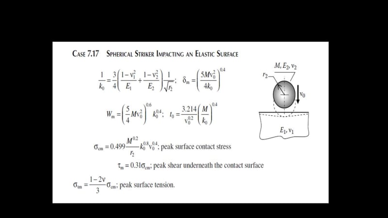
Hi,
Here is my scenario; I have a rock bin (a bin made of rock for rocks, yes it is in an underground mine) with a hopper and chute at the bottom discharging to a conveyor.
We want to install a plate at the bottom of the bin to block any rock entry in the chute.
I am using a worst-case scenario for the impact caused by a falling rock on the protective plate. (max height, max size, maximum impact in the normal axe)
What I know : rock size and max velocity at impact.
What I do not know : Modulus of Elasticity of rock
Assumption; rock will absorb 0 energy
Here are the formulas and steps I am using to design the plate:
1. I am calculating the maximum allowable Force from the Impact using stress on a plate formula and the Steel Yield Strength:

2. With the Max Allowable Force found in step 1, I calculate the deflection:

3. With the Impact Load Formula, subbing the deflection found from step 2 as the travelling distance, I calculate a theoretical impact load.

If the theoretical impact load calculated in step 3 is higher than the allowable force calculated in step 1, I re-iterate the steps with a thicker plate until I achieve a theoretical impact load with security factor lower than the allowable force. (Next steps is to optimized with stiffeners, but I am not quite there yet)
Is my thinking correct? Am I over-simplifying?
I have read a couple of threads on the subject (84200, 74498, 36240 & 77905) but I have not found the steps to be a 100% clear to my linking. I am thinking, hopper, chute and bin’s engineers must do those calculations often, and a straightforward process to achieve those designs must exist. Please let me know if I have to take out my pink glasses.
Also, please note that I am limited resource wise with Mark’s Standard Handbook for Mechanical Engineers, Handbook of Steel Construction (CISC) and google search. So please do not send me a reference of a book I have to purchase and me trying for hours to find a bypass to acquire the said book![[dazed] [dazed] [dazed]](/data/assets/smilies/dazed.gif)
Thanks!
Here is my scenario; I have a rock bin (a bin made of rock for rocks, yes it is in an underground mine) with a hopper and chute at the bottom discharging to a conveyor.
We want to install a plate at the bottom of the bin to block any rock entry in the chute.
I am using a worst-case scenario for the impact caused by a falling rock on the protective plate. (max height, max size, maximum impact in the normal axe)
What I know : rock size and max velocity at impact.
What I do not know : Modulus of Elasticity of rock
Assumption; rock will absorb 0 energy
Here are the formulas and steps I am using to design the plate:
1. I am calculating the maximum allowable Force from the Impact using stress on a plate formula and the Steel Yield Strength:

2. With the Max Allowable Force found in step 1, I calculate the deflection:

3. With the Impact Load Formula, subbing the deflection found from step 2 as the travelling distance, I calculate a theoretical impact load.

If the theoretical impact load calculated in step 3 is higher than the allowable force calculated in step 1, I re-iterate the steps with a thicker plate until I achieve a theoretical impact load with security factor lower than the allowable force. (Next steps is to optimized with stiffeners, but I am not quite there yet)
Is my thinking correct? Am I over-simplifying?
I have read a couple of threads on the subject (84200, 74498, 36240 & 77905) but I have not found the steps to be a 100% clear to my linking. I am thinking, hopper, chute and bin’s engineers must do those calculations often, and a straightforward process to achieve those designs must exist. Please let me know if I have to take out my pink glasses.
Also, please note that I am limited resource wise with Mark’s Standard Handbook for Mechanical Engineers, Handbook of Steel Construction (CISC) and google search. So please do not send me a reference of a book I have to purchase and me trying for hours to find a bypass to acquire the said book
![[dazed] [dazed] [dazed]](/data/assets/smilies/dazed.gif)
Thanks!


