Continue to Site

Eng-Tips is the largest engineering community on the Internet

Intelligent Work Forums for Engineering Professionals

  • Congratulations GregLocock on being selected by the Eng-Tips community for having the most helpful posts in the forums last week. Way to Go!

Design of a plate with Impact Load from a Rock 4

Status
Not open for further replies.

IGSAM

Mechanical
Apr 12, 2015
12
Hi,

Here is my scenario; I have a rock bin (a bin made of rock for rocks, yes it is in an underground mine) with a hopper and chute at the bottom discharging to a conveyor.
We want to install a plate at the bottom of the bin to block any rock entry in the chute.
I am using a worst-case scenario for the impact caused by a falling rock on the protective plate. (max height, max size, maximum impact in the normal axe)
What I know : rock size and max velocity at impact.
What I do not know : Modulus of Elasticity of rock
Assumption; rock will absorb 0 energy

Here are the formulas and steps I am using to design the plate:
1. I am calculating the maximum allowable Force from the Impact using stress on a plate formula and the Steel Yield Strength:
image_noc9rj.png

2. With the Max Allowable Force found in step 1, I calculate the deflection:
image_axegg4.png

3. With the Impact Load Formula, subbing the deflection found from step 2 as the travelling distance, I calculate a theoretical impact load.
image_e8hitp.png


If the theoretical impact load calculated in step 3 is higher than the allowable force calculated in step 1, I re-iterate the steps with a thicker plate until I achieve a theoretical impact load with security factor lower than the allowable force. (Next steps is to optimized with stiffeners, but I am not quite there yet)

Is my thinking correct? Am I over-simplifying?
I have read a couple of threads on the subject (84200, 74498, 36240 & 77905) but I have not found the steps to be a 100% clear to my linking. I am thinking, hopper, chute and bin’s engineers must do those calculations often, and a straightforward process to achieve those designs must exist. Please let me know if I have to take out my pink glasses.
Also, please note that I am limited resource wise with Mark’s Standard Handbook for Mechanical Engineers, Handbook of Steel Construction (CISC) and google search. So please do not send me a reference of a book I have to purchase and me trying for hours to find a bypass to acquire the said book [dazed]

Thanks!
 
Replies continue below

Recommended for you

You might be over engineering a bit but theres no downside to that at this stage. Beaware that good practice is to never allow your bin to run empty, that way the remnant rock bed absorbs or deflects the impact forces and you will have a lot less maintenance in the area.
 
I think you are over thinking and thinking in a confusing way. The work done by a falling rock shall be as simple as m*g*h, or weight of rock times distance of fall, plus the energy required to stop the fall. Seems you are over simplify the matter.
 
If this becomes a lengthy discussion , the OP needs to advise whether the bin is truly vertical or inclined at say 70 degrees. And I might be more worried about abrasion on the bin walls. Have the walls been rebarred??
 
FYI. Link

BTW, I think Miningman's comments are just you need.
 
The F_avg considered by you will give you a lower value than the instantaneous maximum force. Better way is to estimate the stiffness(k) of the plate from dimensions and support locations and expected point of impact(formula below). The stiffness will vary depending on point of impact. Then the the following equations can be used.
image_fy4fm6.png

After you get x then the maximum instantaneous force is
image_gmtdg1.png

Now you can calculate the stresses using the max allowable stress formula.
Using the same set of formulae you have used
image_umkpqt.png

But keep in mind, the stiffness may be higher if point of impact is closer to the edges. Also details of plate support should tally with the model considered.

Engineers, think what we have done to the environment !
 
@mm:
Can you explain? Is this reinforcing or material added for wear resistance? I've not heard the term before. Thanks...

Rather than think climate change and the corona virus as science, think of it as the wrath of God. Feel any better?

-Dik
 
Dik , the general layout as described by the OP can expect to see the passage of upto 2 million tonnes per year. Abrasion is an almost certainty. IN an effort to reduce / resist / minimise this wear , it is normal to install 2 metre long rebar on about a 1.2 metre square pattern . Any steel plates installed are in addition to these rebar. They are typically hi manganese steel and are designed to be replaced periodically. and are typically 1 inch thick. The rebar helps knit the rock mass together as well as reduce abrasive wear. Such a facility might have a life expectancy of 20 years or so with major repair / rebuild every few years depending on site specific conditions. If there is a more severe operational location , I have yet to learn of it.
 
Thanks... I'd never heard of the term... just led a sheltered life, I guess.

Rather than think climate change and the corona virus as science, think of it as the wrath of God. Feel any better?

-Dik
 
Thanks everyone for your response,

@Miningman,
The bin is a 40ft height in verticality (not true verticality, as 25years of ops tends to shape a wall).
The bin constricts at the end (the hopper) to fit the chute, which feeds the conveyor. Only the hopper and the chute is lined, the vertical walls is straight on rocks with fragments on what use to be ground support rods (rebars). Problem is we have to empty the bin if we want to install a protective plate and protect any rocks from entering the chute.
The big idea here, and as you work in the mining field you might have another option to propose, is to secure the discharge chute to be able to change the liners. We use to completely empty and clean the bin, sending workers with the jackhammer and the high-pressure hose, but rising safety concerns put a stop to that.
Other alternative:
Shortcrete is a month shutdown of the bin, and does not last from shutdown to shutdown.
Liner Handlers: I am testing the water with suppliers
Head Cover : contractors use them for ore bins but that's not what they were design for.

@Goutam Freelance
Thank you very much for the information! I will explore with those.
 
Sounds like you need an inflatable bin liner. Last ones I used were designed for 8 feet diameter. Supplier was in Ontario but too long ago for me to remember. Otherwise , fill the bin , send men in from the top with scaling bars and slowly draw the muck from the bottom.T
 
https://www.engineersedge.com/calculators/uniform_...[/URL]

2. With the Max Allowable Force found in step 1, I calculate the deflection:

3. With the Impact Load Formula, subbing the deflection found from step 2 as the travelling distance, I calculate a theoretical impact load.

If the theoretical impact load calculated in step 3 is higher than the allowable force calculated in step 1, I re-iterate the steps with a thicker plate until I achieve a theoretical impact load with security factor lower than the allowable force. (Next steps is to optimized with stiffeners, but I am not quite there yet)
]

Dear IGSAM , I did not look in detail to the previous responds and am not in a position being offensive to any of the responders however, with procedure you want to follow , you may get undesirable plate thickness. If the theoretical impact load calculated in step 3 is higher than the allowable force calculated in step 1 , you will increase the plate thick. and you will get higher impact load than the previous iteration. I will not suggest to follow... I did not look in detail the previous responds , but apparently the applicable impact load based on energy approach is not mentioned.

Let me explain some concepts;

-If the drop object and the supporting ( beam, rod , in this case plate) fully elastic and no energy dissipation, the dynamic load is a function of static deflection
Pdyn = W ( 1 + SQRT (1+2h/ Δst) W = weight falling from a height h. Δst = is the static deflection for the weight W.

- The following snap from the Roark’s Formulas for Stress and Strain based on the above formula..

impact_stress_xkw824.jpg


di and σi are deformation and stress for the impact loading.

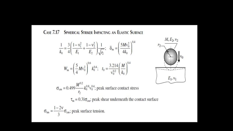
- In your case, restitution for natural rock and friction with the surface reduces the impact stress. With a conservative assumption , spherical rock striking to elastic surface ;


spherical_striker_cf1koq.jpg


The above is a snap from the book Formulas for mechanical and structural shock and impact by Szuladzinski .

You may provide more detail to get better responds. Getting a thicker plate is not always the solution.

Good Luck..
 
I work in this field and I understand the configuration you have but not your goal. Are you trying to shut off the rock flow so you can do maintenance on the hopper and chute work to the conveyor?

How is the rock flow to conveyor controlled during operations? I assume either a vibrating feeder or is the conveyor a belt feeder?
 
all deference to Roark, but "h/d" is going to be a staggeringly high number.

all impact calc devolve to answering the question "how long is the impact (time interval) ?" "how long does it take for the falling/moving object to come to rest ?"

another day in paradise, or is paradise one day closer ?
 
Status
Not open for further replies.

Part and Inventory Search

Sponsor