Continue to Site

Eng-Tips is the largest engineering community on the Internet

Intelligent Work Forums for Engineering Professionals

  • Congratulations waross on being selected by the Eng-Tips community for having the most helpful posts in the forums last week. Way to Go!

+Design of a Three phase squirrel induction motor connected to a mechanical load system diagram

Status
Not open for further replies.

xMeck

Electrical
Nov 5, 2019
9
I was just curious how far off I am with my current design from making my desired design. I want to produce a Three phase squirrel cage induction motor but I cant say I'm 100% confident on how to do so, currently I just want to run the design with default parameters before I start to change the values of the friction coefficient, rated stator voltage, number of poles and the rated frequency. The design is a small section of what I need to do compared to the testing although I dont have a clue how to fully make the system into a three phase squirrel induction motor as it seems I cant find anything similar anywhere. Just to add I am using PLECS 4.4.4 software.
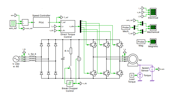
three_phase_ougymz.png
 
Replies continue below

Recommended for you

I'm not sure if I can help, but... what are you are trying to accomplish (what will you do with the model).

Also perhaps try running some simple test cases to see how your model does compared to how you think it should do.

=====================================
(2B)+(2B)' ?
 
This part of your drawing is the three phase induction motor.
image_qgyl9f.png


Bill
--------------------
Ohm's law
Not just a good idea;
It's the LAW!
 
@waross So I should be able to just add a three phase squirrel cage induction motor instead of a three phase motor and I should be good to go? I wish I had more experience with PLECS but its a new piece of software for me that I am still trying to get used to. Assuming PLECS have a squirrel cage motor although I couldn't find one previously.

@electricpete Im mainly hoping to get to grips with the system and see how it runs, first with default parameters then ill be changing the number of poles, stator voltage, frequency etc to see what changes.
 
OK, Got it. You are working with a software program and not trying to build an actual motor.
It seems as if you may be trying to design from scratch a complete variable frequency drive system.
A couple of pointers:
Three phase induction motors are plentiful, Off-the-shelf.
Take a look at the Cowern papers for a very good introduction to many aspects and characteristics of induction motors.
Cowern Papers
The electronic portion of your drawing is normally combined into one device called a Variable Frequency Drive.
Search this forum for a lot of information on VFDs.
A couple of tips:
An induction motor takes reactive current to establish the rotating magnetic field.
This reactive current is 90 degrees out of phase with the real or load current, and changes slightly under load.
A Watt-meter will show the sum of the load plus the losses, but while not perfectly linear with loading due to the losses, a current value derived from the Wattage will be a much more accurate indication of loading then an Ampere reading.
Torque curves.
There are many published torque curves for several designs of standard induction motors.
Almost all of the curves that you will find are for Direct On Line starting.
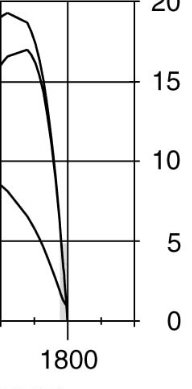
When using VFDs, the motor is operated in the last 100 RPM of the curves.
That is from the peak of the torque curve to100% speed.
The difference between the synchronous speed and the actual speed is called the slip-speed.
The difference between the applied frequency and the frequency corresponding to the actual frequency is called the slip-frequency.
The slip frequency is the frequency that the rotor sees.
Start with a typical torque curve that is labeled across the bottom in motor RPM. eg: (0-1800 RPM)
reverse the numbers so that 1800 RPM is at the left and 0 RPM is at full speed.
This is now your slip RPM.
This may now be used with good accuracy for any applied frequency.
If the slip speed is 40 RPM, the slip speed at full torque will be 40 RPM slip at any applied frequency within reason.
Another thing that you should be aware of is saturation.
As the applied voltage is increased, the magnetic field increases until magnetic saturation is reached.
If the applied voltage is increased further, the current will increase rapidly and the motor will burn out, possibly in minutes.
But the iron core inductive reactance that limits the current when not saturated is frequency dependent.
If you double the frequency you may also double the voltage without saturating. (Subject to suitable insulation.)
We use a number called the Volts per Hertz ratio.
For your example, 240 Volts and 60 Hertz, the V/Hz ratio is 240V/60Hz or 4 Volts per Hertz.
This is one of the things that a VFD does; It used Pulse-Width-Modulation to reduce the effective applied voltage to match the applied frequency.
This is a simplification.It is capable of a lot more.
Torque: You don't control the torque. The load demands torque and the motor meets tha demands as long as the demnds are within the motor capability.
Good luck.
(It's late and I don't have time to proof read. If i have made silly mistakes, let me know and I will make corrections.)


Bill
--------------------
Ohm's law
Not just a good idea;
It's the LAW!
 
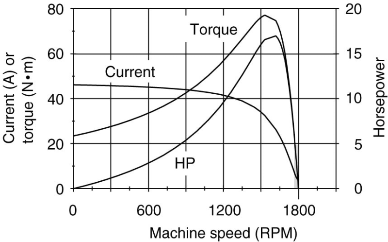
A typical speed torque curve. While not stated, this motor is probably rated at 7.5 HP.
It will deliver 200% to 250% if it is allowed to but it will overheat.
Prolonged operation above the rated HP may lead to motor burn-out.
image_xkeons.png


A VFD is intended to operate a motor in this portion of the curve.
image_qo3ssf.png


Bill
--------------------
Ohm's law
Not just a good idea;
It's the LAW!
 
Torquecurve_ks8ele.png
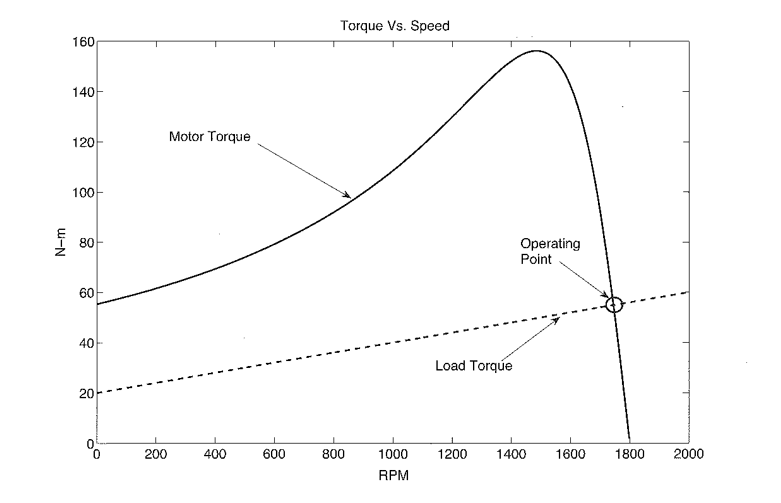
Appreciate the informative reply @waross still unsure whether @s do work in replies. Also, I don't think I have given a proper insight as to what I am doing/want to produce, I'm basically wanting to design a three phase squirrel cage inductor motor which I currently have set up in PLECS as just the three phase squirrel cage inductor block, which id then want to be connected to a mechanical load system diagram. So the main problem I have been having is with the mechanical load system side and how to go about designing it and with all the different systems already made out there it can be a little confusing for a beginner, as I know the background theory related to the induction motor which ill add an image of what ill be comparing to, and what I am working with, but not so much experience on how I would connect things together.
Back onto the project, the system I plan to use wouldn't need an inverter drive to be added. I feel like I am overcomplicating the design for myself like the above example, when I need the key components, inputs and outputs of the system. Then from there I would just be keeping the default values that PLECS 4.4.4 has provided, doing a simulation and taking notes of the results, then just changing one value at a time, stator voltage at 220V, rated frequency at 60Hz, number of poles, lets say 6 poles, along with changing the friction of coefficient to 0.5 then taking note of each result and how it changes the system. For me its a good way to get an understanding of what does what and how each section affects the system if that makes sense.

Id basically want to be able to include simulations for the load value changes, stator voltage frequency changes, and then calculate the synchronous speed and the slip speed of the machine which is also in my theory when it comes to calculators like the slip speed is s = ns - nr rpm or shown as a percentage, ns - nr / ns x100%. I will still be attempting to create the design using PLECS 4.4.4 and ill hopefully be able to send updates when I make progress.

I do appreciate your reply also as the information does help but like yourself its 8am currently and I've gone without sleep so the information tough to take in right now haha. Thanks again.

Edit: Funnily enough we have a similar theory image, hadn't seen your message prior to sending my own, the theory side of it is understandable for me but I have a pain with practical sides unless im hands on with something
 
Then from there I would just be keeping the default values that PLECS 4.4.4 has provided, doing a simulation and taking notes of the results, then just changing one value at a time, stator voltage at 220V, rated frequency at 60Hz, number of poles, lets say 6 poles, along with changing the friction of coefficient to 0.5 then taking note of each result and how it changes the system. For me its a good way to get an understanding of what does what and how each section affects the system if that makes sense.

I agree it may be a good idea to play with the model, starting simple, and see if the results make sense. You can post results here if they don't make sense and maybe we'll have some comments.

I don't have any experience with this software and I'm guessing most here don't, so that will limit the ability to help you.

I'll mention there are two basic equivalent circuit models for an induction motor: the steady state equivalent circuit and the transient (aka dynamic) equivalent circuit.

The steady state equivalent circuit for an induction motor (often referred to simply as the equivalent circuit) as the name implies can predict steady state results. It can do so with pretty simple circuit calculations, no need for a numerical time-domain simulation. You can also mis-apply the steady state equivalent circuit by plugging it into a circuit simulation and performing a "transient analysis"... the results may be close but they will not be right.

The transient/dynamic equivalent circuit for an induction motor is more complicated as shown in figure 2 here, and that's what is preferred for dynamic analysis. Numerical simulations are required to use this circuit and typically coordinate transforms are involved. I personally find Paul Krause's book "ANALYSIS OF ELECTRIC MACHINERY AND DRIVE SYSTEMS" to be helpful. There are also a variety of drive types, which can complicate things further. Also things like iron properties are rarely modeled correctly so none of these simulations are perfect.

=====================================
(2B)+(2B)' ?
 
For the best understanding, look at how the basic units change.
Current:
The current is composed of real current in phase with the applied voltage and reactive current at 90 degrees to the applied voltage.
It may be more valuable to see how the reactive current and how the real current respond to changes than looking at the total current.
RPM:
Example:
An unloaded motor may approach synchronous speed. The change in RPM from no load to full load on a motor rated for 1760 RPM will approach 1800RPM-1760RPM)/1800RPM = 0.0222 or 2.22%
A change of 2.2% may seem insignificant, BUT;
The slip frequency on the example motor will be 40 RPM at full load. The slip frequency as a percentage of 40 RPM will track very well with the load on the motor.
It will directly relate to Load plus losses.

Bill
--------------------
Ohm's law
Not just a good idea;
It's the LAW!
 
Power Factor:
This is a ratio of two changing factors acting at 90 degrees to each other.
A poor power factor on an unloaded motor may be a high percentage of a low number.
When you change a parameter, look first at the in-phase current and at the reactive current.
Then consider the change in power factor.

Bill
--------------------
Ohm's law
Not just a good idea;
It's the LAW!
 
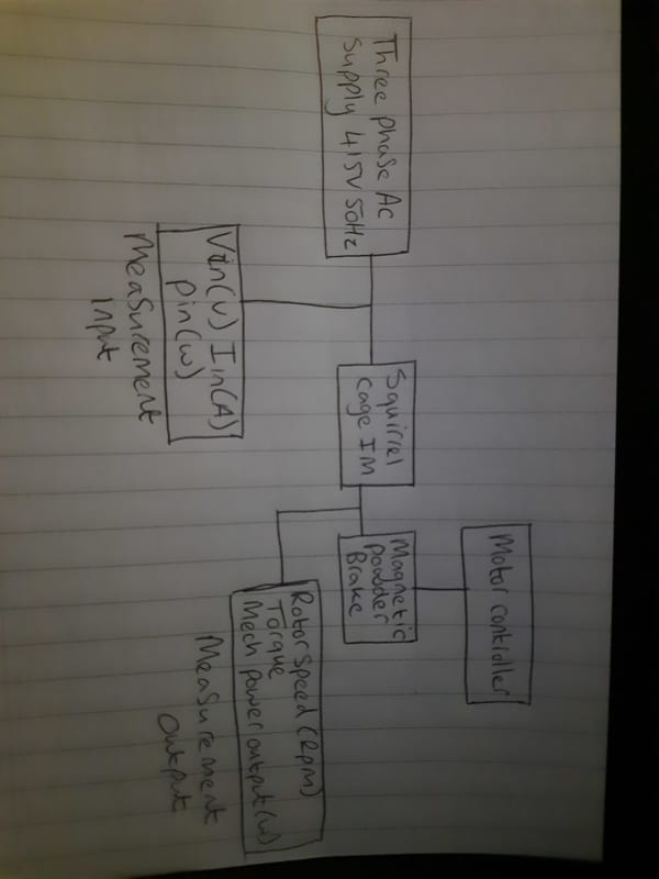
Ok so on further research I have come up with a new diagram but one I have not produced on PLECS just yet, the fun part will be finding all the block diagrams for what I need as ive never used the software haha. But basically I am going to have my three phase ac supply connecting to the stator windings of my squirrel cage induction motor, in between the motor and supply I want to have my measurement devices reading the input values, this will be the usual power, voltage and current readings. I will then connect the squirrel cage motor up to a magnetic powder break which basically just slows down the motor using the powder inside combined with the increase of current on the magnetic field, for this I have connected a motor controller, and finally having an output measurement connected measuring the Torque, Rotor speed in rpm and the mechanical power output. SO compared to my previous diagram that I posted this is a lot simpler. The supply and induction motors are basically blocks, so the squirrel cage motor comes with the 3 connections for the supply and a further output for the brake, the motors parameters are there to be changed inside the programme PLECS. So that side of things is simple enough and only the values I want to change need to be changed such as the frequency, voltage, coefficient and number of poles. The magnetic brake I'm not exactly sure what to do with at the moment as I cant find a block for that. The input measurements I can do using the normal meters, which should be similar with the outputs.
20210407_061825_e0dnpz.jpg

@waross @Electricpete
 
See if you can program a Watt meter and a VAR meter. Use Watts, Vars and Voltage to derive your currents.
That will teach you a lot more than an ammeter reading.

Bill
--------------------
Ohm's law
Not just a good idea;
It's the LAW!
 
That is true @waross and something that hadnt crossed my mind to be honest, I feel like finding the compared block for the magnetic powder brake will drive me crazy when it comes to PLECS as ive either missed the blocked or need to use something else in its place.
 
Status
Not open for further replies.

Part and Inventory Search

Sponsor