Continue to Site

Eng-Tips is the largest engineering community on the Internet

Intelligent Work Forums for Engineering Professionals

  • Congratulations KootK on being selected by the Eng-Tips community for having the most helpful posts in the forums last week. Way to Go!

Design of a Typical Gate

Status
Not open for further replies.

Orsted

Civil/Environmental
Apr 3, 2019
22
Hi fellow engineers,

[highlight #EF2929](Not sure where to post this please advise me if I'm in the wrong forum)[/highlight]

This might be quite long. Please bear with me and I'll say this in advance, Thank you for your time and response.

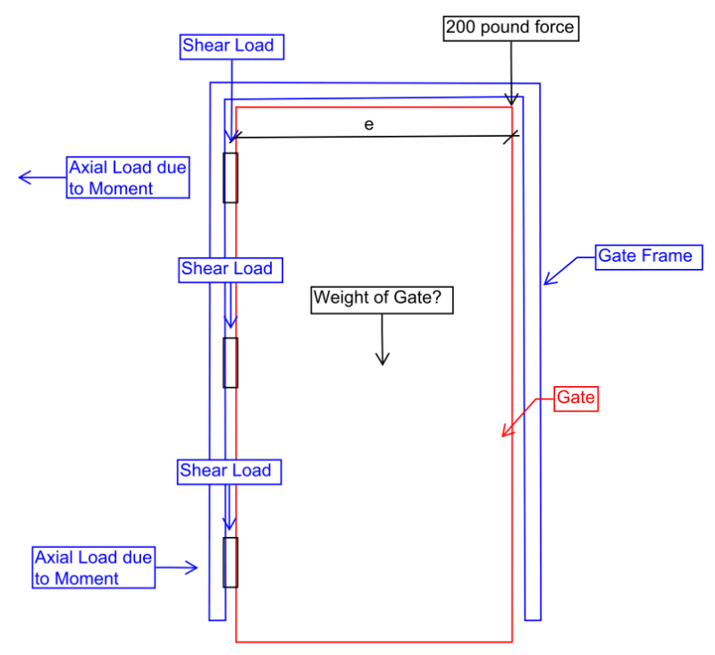
I cant seem to find a guide in designing a gate so I've used the minimum load of 200 lb applied in any direction same as railings since the gate I've been designing has railings along/beside it.

Now wondering if the loads I've applied and how I design it is practical/applicable.

The image below is just a sample since what's important for me is how the loads will be applied then design the members/connections from there.

[ol 1]
[li ]Apply a 200 lb force on where I think would produce the largest reactions. [/li]

[li] Compute the load of the gate and then summation of forces that will be applied to my hinge[/li]

[li] Then finally getting the axial load and shear forces as shown in the image[/li]
[/ol]

My queries are:
1. Is my design practical or is there a better way in doing this.
2. Do I need to consider wind load?
3. Is there a design guide for this?.​


image_locx0e.png
 
Replies continue below

Recommended for you

I'm all for engineering even mundane things but unless you're making 1 million of these just build the gate with off the shelf hardware and best guesses on materials. If it's not strong enough then make it stronger. Really shouldn't require much engineering.

That said, your forces look reasonable. Only thing I'd add is if the gate is fully open then the hinged are no longer axial reaction but lateral reactions causing torsion on the frame.

Ian Riley, PE, SE
Professional Engineer (ME, NH, VT, CT, MA, FL) Structural Engineer (IL, HI)
 
TehMightyEngineer said:
Only thing I'd add is if the gate is fully open then the hinged are no longer axial reaction but lateral reactions causing torsion on the frame.

Yes, I'm considering also if it's open.

Thank you.
 
The gate itself is rarely an issue. The supporting frame on the hinge side is, and if too flexible, the gate will sag. But that is usually problematic with a freestanding post. With a rigid frame like you apparently have, it is more like a door than a gate.
 
hokie66 said:
The supporting frame on the hinge side is, and if too flexible, the gate will sag. But that is usually problematic with a freestanding post. With a rigid frame like you apparently have, it is more like a door than a gate.

Yeah I agree. Thank you
 
Clients have asked me to design things like this in the past. My response has always been “do you really want to see a structural engineer’s answer to a gate???”

The trouble is, if we try to design this, we then apply a structural code of practice to something as non-structural and mundane as a gate, which is not entirely appropriate. I’m with the above - just blacksmith it!!

If you really want to go first principles on it however, your approach looks reasonable.
 
I do not know of a "gate code" and I agree, you really don't want an Structural Engineer's solution. First, since there is no specified design loading, but you are using the 200# from the railing portion of the code, I see a problem with that thought process. If this gate is part of an emergency exit, I would consider the load too low and maybe in the wrong direction. If it is not an emergency exit for a lot of people, I would be much less worried about it. People gravitate to an exit in an emergency but not a railing. The railing turns them towards a true exit.

If the gate failed under loading, what would happen at the worse? If there are steps right outside the gate, that is different from there is no change in elevation.
I agree with the other, if this is just a quantity of 1 or 2, "make it stout and get it out".
 
No.

The shear load on the hinges is near-negligible: Nearly any pair of commercially-bought hinges will hold the weight of the gate. You have three sketched. The difficulty will be installing (by welding, screws, lag bolts, or through bolts) the three hinges aligned close enough that they will not bind by being out of alignment.

The gates I see failing all sag. And yo have sketched nothing to indicate any resistance to sag.

They sag two ways, sometime both at the same time. The "rectangle" gate mass will sag, or the hinge-side frame will sag. If the "rectangle" sags, the hinges stay in place and the far side droops towards the ground. Often hits the ground since an outdoor gate rarely is in flat, level ground. To reduce this "rectangle" sag you MUST provide moment resistance at all four corners of the frame, or (assume pinned corners) provide a triangle member to carry the moment load. Or both. The problem with the moment-resistant corners and frame is that their weight increases the force they must resist. The problem with a triangle member (even a wire and turnbuckle) is appearance.

If the hinge-side load is too great, the hinge-side frame leans over. You have a little bit of a help here - the tall hinge-post will be braced by the gate upper bar and the right-hand (latch-side) vertical post. But their combined resistance to sag depends on the two foundations and the resistance over time of the dirt/rock/gravel/mud the posts are sitting it.

Traffic through the gate will erode the ground between the two verticals unless you lay in sidewalk or concrete steps. Walkway erosion in the center will, over time, reduce resistance to the posts' tendency to sag towards the latch side. You can reduce this sag by building a latch that holds the gate weight partially, but that makes closing the gate more tedious.

Now, you do need to determine WHAT the gate "square" will be made of. That establishes the gate weight -> See hinges above. See moment-resistant corner "design" above.

More important, "what" the gate is made of (sheet of plywood 3/4 or 1 inch thick? Solid wood sections glued and doweled together? Sheet of metal? Metal 1/2 rods or bars in a frame? Metal frame around a lighter wood in-fill?) Will the fill material do anything but increase weight? Will its members increase moment resistance against sag?
 
Status
Not open for further replies.

Part and Inventory Search

Sponsor