Continue to Site

Eng-Tips is the largest engineering community on the Internet

Intelligent Work Forums for Engineering Professionals

  • Congratulations cowski on being selected by the Eng-Tips community for having the most helpful posts in the forums last week. Way to Go!

Design of an angle in bending

Status
Not open for further replies.

HanStrulo

Civil/Environmental
Apr 16, 2021
117
Hi Everyone,

I have an elementary question about angles in bending.

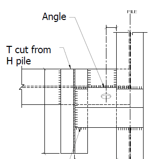
I have an angle in bending. Length of the angle is about 15" and the load is applied in the middle of the angle. (There is a sketch below).

My question is: since the load is on the middle of one leg and not on the geometric center of principle axis. How to calculate the bending resistance of the angle? do i have to check something else other than bending?
eccentric_tie_back_design_cr82gx.png


Thanks alot
 
Replies continue below

Recommended for you

Is this an elevation or section? I'm having trouble figuring out the drawing.
 
It still isn't fully clear what the situation is. I assume that threaded rod is some form of ground anchor? Remember we have no idea what you're trying to accomplish so although your sections may make sense to you, we don't even know what structure we're looking at so they aren't as helpful as they may be to you.
 
Keep the "span" of your angle to a minimum needed to accommodate the drill casing and bit. Then the angle really should not be bending. Think of the angle as a flat steel plate simply supported at the soldier beam flange by the upper weld and supported by the lower angle leg that is welded to the soldier beam. With the tieback's bearing plate sitting on top of the angle, the tieback load will be supported by the tieback anchor's bearing plate, the two angle welds, and the lower angle leg in compression. I use an 8" x 8" x 1" thick steel angle and then cut the lower leg to give me the required tieback angle.

 
I think there is more than one way of doing this.

I might do 2 simple analysis. See below....

First, I would imaging a simply supported beam Spanning between A & B with a point load applied in the middle of it (PL/4). That will get the max 'positive' bending moment in the upper angle leg.

Then, you could re-calculate the same beam as pinned-fixed to get the max 'negative' moment at B (Steel manual table 3-23 diagram #13).

Another way would be to figure out the eccentricity of the nail from the lower leg and calculated a moment about the lower leg cross section.

Capture_jd5rr0.jpg
 
I would use the flat bar bending formulas shown in steel manual section F11 for your capacity equations. The outstanding angle legs are just 'rectangular bars bent around their minor axis'.
 
Also not clear on exactly what you have, but in general I would just look at bending, torsion, and shear. Not the easiest of analyses, since single angles are interestingly a PITA in terms of member geometries, but not all that hard, either. While you're at it, make a spreadsheet/MathCAD/Smath program for single angles in bending with the load applied eccentrically (away from the shear center) and you'll have a really handy tool for the next long brick veneer lintel you need to design.
 
Thank you every one for the answers.

I apologize my schematics were not clear enough.

I am designing a tie back connection to an H pile using an angle. The tie back is 75 mm eccentric from the H pile so we used a longer angle ( we usually use a short angle with a width equal to the width of the H pile) but this time I used 600 mm long angle.

I have some design aid from the CISC ( SX of an angle) and was wondering if i could use it. I have no idea how to approach an angle in bending. is the design aid inherently not suited for this situations?

Previously, with shorter angles, I only check the compression of the leg with half the tie back load and design the welds.

 
I see a soldier H-Pile wall with horizontal W-section whalers. There could be wood sections (not shown) in-filling between the H-Piles.

The wall is tied back with soil nails.
 
JoelTXCive

THat is true. I am using strands for the tie back but all the elements you mentioned are present in my problem.

Thanks
 
The tieback anchor's bearing plate is normally about 6 to 8 inches square and about 1 to 1.5 inches thick. It should be big enough and thick enough to span from the upper weld to the perpendicular leg of the angle. Therefore, bending of the angle leg is usually of little concern. The main design requirement is weld shear from the vertical component of the tieback anchor. Next is crippling of the lower angle leg.
I don't like the eccentric connection or the (incompletely detailed) sketches proposed by HanStrulo. Refer to his other post on the same problem.

Most tieback connections when there is no tieback wale between soldier beams (i.e., thru-beam connections) include either cutting the front and back soldier beam flanges on one side of the web, drilling the tieback anchor against the soldier beam web, and then beefing up the soldier beam to replace the strength lost by removing the flange sections. This still causes eccentricity and soldier beam twisting. Or, holes are cut through the front and rear soldier beam flanges and web and the tieback is installed without any eccentricity. However, the soldier beam still needs to be strengthened to replace the missing portions of the flanges and web.

 
Status
Not open for further replies.

Part and Inventory Search

Sponsor