Continue to Site

Eng-Tips is the largest engineering community on the Internet

Intelligent Work Forums for Engineering Professionals

  • Congratulations KootK on being selected by the Eng-Tips community for having the most helpful posts in the forums last week. Way to Go!

Design of C-shaped and rectangular core walls

Status
Not open for further replies.

fracture_point

Structural
Mar 7, 2019
58
Hi,

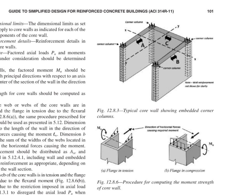
Does anyone have any good references for the design of C-shape concrete shear walls? I'm looking for specific examples where the analysis and design treats the wall as a complete section, as opposed to splitting it into 3 individual planar walls. I have searched through my design books but can't find any good examples.

Thanks!
 
Replies continue below

Recommended for you

Seems to me it's just a large channel. Calculate the properties of the channel and press on.

BA
 
Seconding what BAretired noted. Some caveats though, you need to review the net tension/compression in the individual elements with respect to the effects this has on the shear capacity (tension reduces the concrete shear capacity). Ensure you review the shear in each of the elements against the provided (concrete plus steel) capacity separately, don't review the shear reported by considering the channels as a whole (in the 'flanges' the shear is often opposite directions so cancels if integrating the shear over all three elements (like defining a pier in etabs for example that contains all three elements)).

Etabs for example will allow you to define a pier containing the single elements and the three as a whole to get the required design actions. Other analysis software might have similar capabilities.

But for moment capacity review as a channel with reinforcing, similar to any general concrete shape (lots of software will do this or work from first principles).
 
Shear wall theoretically can resist shear in the plane of the wall only. You have treat the “C” shape wall as two section: the “web” take horizontal force in plane along the “web”; the “flanges” take the horizontal force perpendicular to the web only.
Extra torsion due to the eccentricity of the “C” shape shear wall stiffness center and the horizontal force has to be taken by the shear wall.
Design “C” shape shear wall as normal shear wall design once the horizontal force on each components is figured out.


—————————————————————
Shu Jiang, SE (Nevada). PE(Michigan, South Dakota), PEng (Ontario)
J&J Structural Consulting Inc.
Structural design, analysis, inspection, drawing review and stamping, and connection design
 
This has been a subject of considerable interest to me. In my opinion, how complex the problem is depends on how fancy you want/need to get with this. In it's simplest form, looking at just principal axis flexure and shear, it's pretty straight forward. And I've included a decent reference for that below. Some of the complexities that can arise:

1) Often you've got two channels coupled together with all that implies with respect to coupling beam detailing and stiffness assumptions.

2) If you're doing your ASCE7 load casing by the book, you'll wind up looking at a bunch of non-principal axis P-M investigations. This sucks by hand.

3) There is the question of slenderness limitations for keeping the outstanding flanges from buckling between levels of restraint.

4) There is the question of whether one uses just the designated zones for flexural tension capacity or all of the bars, including those that don't yield.

5) There are the detailing aspects of which bars get tied etc which can we can never seem to full agree upon.

6) There is the question of how much flange width should be considered, both in tension and compression. Codes are finally getting around to chiming in on this.

7) When you're really taxing a flanged wall, as with seismic, there is the business about the final web strut punching through the flange rather than turning the compression around the corner of the tee intersection like a well behaved compression field.

8) Tallish, channel shaped shear walls will exhibit a warping stiffness, as little steel channels do. Looked at in detail, this complicates load distribution between various lateral elements and gets you into to all of the sectorial coordinate business.

I know of very few published resources that contain worked examples of this kind of thing. Here's what I can recommend:

- MacGregor / Wight Concrete text. I think it has a few basic examples of compound shear wall sections.

- Paulay & Priestley's seismic book gets into some examples.

- Most of Taranath's books have strong chapters on the sectorial coordinate business and other aspects. I believe this was the core of his graduate work before he went full on, rock star practitioner.

- This paper's kinda neat: Link

- The program S-Concrete automates much of the P-M work and is a good tool for the investigation of sectional behavior.

c01_hp94xs.jpg
 
One other point reading through KootK's list that popped into my head, is careful consideration of the cracked stiffness of the channel/core. At lower level storeys, the wall will in all likelihood be cracked (Moment exceeds the uncracked moment based on concrete rupture strength), but at higher storeys the wall may remain uncracked. This variation in stiffness should be considered in any modelling, especially under seismic as it affects the dynamics and often load distribution between elements.

What complicates this judgement is for a channel with uniformly distributed reinforcement is that the moment capacity will be significantly different in each principle direction, similarly for each direction of loading if there is coupling going on with other elements the axial loading is likely to be significantly different as well for load going left to right vs right to left. In the past I've tried to lump more reinforcement at the flange tips to even out this effect and try make the axial/moment interaction plot as uniform as possible in all 4 sections (if looking at it in plan at a constant axial load). Definately life can be simpiler with minimising the degree of coupling going on if you don't need coupling to address overall stiffness of the structure.

Many/some of the items on KootK's list should also be addressed via code provisions (depending on where you are in the world), and the commentaries often go into the reasoning for many of the provisions.
 
Thanks everyone for the responses.

KootK - I will look further into your points. My company actually uses s-concrete but I like to personally analyze things by hand to have a thorough understand of the methods the software is using before relying on it. However, it has been very difficult to find information on sectional core walls. It seems typically in my company to split a c-shaped core wall into 3 individual piers and design them individually.
 
OP said:
It seems typically in my company to split a c-shaped core wall into 3 individual piers and design them individually.

Yeah, I've seen that from a lot of big name firms and on a lot of tall, high profile projects. And, when you get into the meat of the possible complexity, you can see why.

 
I've always been wary of modelling/detailing core walls as separate walls with minimal gap between. Consider for a moment what happens to the floor at the corner/gap. In certain directions of loading there is a tension zone at the wall end, and compression zone in the other. Under any loading you will get a differential axial lengthening and shortening in the walls at a corner, and this becomes a compatibility issue for the floor to accommodate these relative displacements over the small gap. Combine this with the fact you are also trying to drag force (and sometimes a lot of force at transfer diaphragms!) into the wall via this bit of the floor and things bet pretty muddy pretty fast in my opinion. If the floor/concrete/reinforcement is damaged in some manner trying to accommodate these relative movement then how does this impact on the load path for these diaphragm forces into the wall. In effect your slab becomes a very short coupling beam lacking shear capacity to accommodate the demands being placed upon it.

In all my time doing peer reviews and raising the possibility of this type of incompatibility with designers for consideration I've only ever seen one designer take measures to address it before I raised it, they took the approach of separating the slab from the walls over some finite length of wall at the ends of the wall so the slab could accommodate these relative movements over the interface without buggering the floor.

By splitting it you of course lose any stiffness benefit, but it can be a useful tool for softening a structure and getting a less torsional response for example if you have an irregular layout.

If you are splitting it for the analysis, and then joining it in reality for your detailing this would invalidate any design/analysis. I've seen self-delusional engineers try justify this approach to themselves, you might as well be analysing a different structure because that's the impact of assuming that this approach is a valid simplification. How far from reality might depend on a few things like how tall, differences in response/stiffness, it just cannot be generalised.

So in summary, ensure you consider the consequences of any simplification I guess.
 
Agent666- Thanks for the discussion. The more experience people in my office seem to split a C-shaped core wall into 3 piers in analysis and design, when in reality these ARE joined as one composite section. I have trouble justifying exactly this behaviour myself which is why I am raising these questions here to further my own knowledge before I can really challenge my seniors with any justification.

If I understand what you are saying... If we do split the walls into 3 with some kind of separation joint, there will be a differential axial deformation between adjacent walls, and you are explaining this will cause some issues with the slab, am I understanding this correctly? Do you have any additional literature on this for me to further my knowledge?

 
The Institution of Structural Engineers published an excellent guide in 2015 that addresses the design of shear walls: "Stability of buildings. Part 3: Shear walls". I can't recommend this guide and the other 3 parts enough.
 
Avscorreia - you don't happent to have a copy to hand you could send do you? I can't find it online and would have a hard time justifying buying it as it's not my governing code :(
 
I'm sorry, but it's copyrighted material.
Parts 1 and 2 can be found on the internet with a simple search and that can already show the kind of information you can find there. I'm not suggesting that you look for them, just commenting.
 
There is some discussion of compound walls in the "Seismic Design of Reinforced Concrete and Masonry Buildings" by Paulay/Priestley.
 
fracture_point, yes that's exactly what I am saying regarding the floor. I'm not aware of anything written about this effect, but I have seen evidence of this type of damage in photos from recent earthquakes here in NZ.

Additionally if you split it and provide reinforcement for this condition and then join them your moment capacity is completely different. It wants to attract load as a channel, and its likely your nicely balanced 3 wall scenario with equal moment capacity in each direction is now unbalanced in the sense you will have much higher capacity in one direction vs the reverse direction. In ductile structures this can lead to racking, or permanent deformation in the weaker direction with each cycle (basically this is bad).

I mentioned above about the need to try and match the moment capacity of the 'joined' channel/core in one direction with the reverse direction capacity for good ductile response. Its a bit like a concrete beam that has a grossly different capacity in positive vs negative flexure. It's well known that as the degree of mismatch in the top vs bottom reinforcement increases, the ductility/curvature the beam can achieve actually decreases. Often in codes for beams, they address this aspect by limiting the ratio of tension to compression steel depending on the degree of local ductility demand that is required to achieve the plastic portion of the rotation within a plastic hinge.

The same applies to walls, in my own code it basically addresses the racking effect by requiring the strength in one direction to be within a certain percentage of the strength in the opposite, otherwise you are penalised with additional factors, multiply this by a number of cores and you can inadvertently end up with ductile torsional response (one core yields, while other is much stronger than assumed due to analysis assuming separate walls vs joined in reality) which is highly undesirable and your initial analysis is basically out the window as the structure is responding in a completely different manner than your analysis predicted.

Additionally if your wall system is much stronger than assumed in the design due to joining the walls in reality, then the overstrength forces are larger to. If applying capacity design principles you are potentially underestimating the design actions and not actually achieving the capacity design protection of elements that actually require it (for example your foundations in the case of cantilevered core, or in transfer forces due to any podium kickback forces, etc).

 
Agent666 said:
I've always been wary of modelling/detailing core walls as separate walls with minimal gap between

I do not believe that this is what people are doing. I think generally they model the walls as monolithic, but then pull the wall forces/moments/shears out of ETABS for each individual wall separately and design as such. Still need to consider the longitudinal shear at the interface.
 
Retrograde, Agent666 - Yes, most people in my office are modelling the walls as monolithic but using individual pier labels for each planar wall that makes up the C-shape, and then design the reinforcement individually. My initial thought was if we can combine the 3 piers to behave like a panel in the model and design them as such, as a more economical method but it seems to be rather complicated and I can't find any literature that discusses it in depth. All that I've read so far seems to just brush over it without any design examples.

I'm trying to verify the validity of the numbers I am getting from the s-concrete c-shaped core calculations
 
Retro,

What would be a simple way to consider the longitudinal interface shear between the walls when adopting an individual pier/wall design strategy? This would also apply to precast cores and stitch plate design.

EDIT: A thread I started a few years ties into this discussion somewhat. LINK

 
Trenno said:
What would be a simple way to consider the longitudinal interface shear between the walls when adopting an individual pier/wall design strategy?

I'll take one of two approaches depending on the type and quality of information available to me:

1) Take the unit shear in the web element and apply it to the longitudinal joints.

2) Take the forces in the flanges and assume they've got to make it over into the web via the longitudinal joints via some reasonable distribution of shear over the height of the building.

In the past, I'd assumed that the longitudinal shear could be redistributed over the height of the building somewhat. And I still do for seismic walls with plastic hinging. Unfortunately, that seems to be in consistent with contemporary ACI provisions for beams with composite concrete flanges where you have to stick closer to a VQ/It model.

One thing that I've always been curious about is how other folks are making the longitudinal joints work. Typical detailing has overlapping tie sets at the corners. It would be easier in the field not to overlap the ties but I've always assumed that it was done to create healthy, longitudinal shear friction joints at the corners. That said, I've not seem anybody other than myself actually check it that way.

 
I was thinking more in terms of general multi-wall core arrangements with numerous L and T joints, so as to be able to apply it to all typical mid/high rise cores.

 
Status
Not open for further replies.

Part and Inventory Search

Sponsor