Eng-Tips is the largest engineering community on the Internet

Intelligent Work Forums for Engineering Professionals

Design of low pressure flanges 4

Status
Not open for further replies.

VishalSathe

Mechanical
Feb 2, 2008
4
0
0
BE
Hello, I am currently working on a case for re-rating of pressure vessel.
The vessel is currently designed for 6 kPa and needs to be re-rated for 20 kPa.
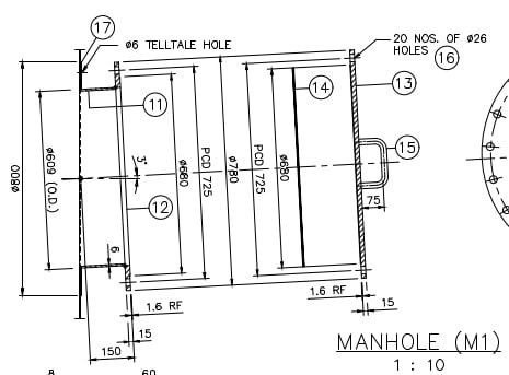
I am checking the manway flange design (its a non standard flange- ring type flange with plate used as blind cover).
I tried ASME Appendix 2 design, however its not passing in gasket seating condition, however there is no overstress in operating condition.
My question is, since this is an existing vessel, is it necessary to re-check the flange design for gasket seating condition?
I would appreciate if you have some idea about similar issue.
 
Replies continue below

Recommended for you

Are you sure this is a PV?
what code was it designed to?

what's a "ring type flange" exactly?

6kPa (0.06 bar / 0.9 psi) is not normally a PV.

Try TEMA?

But yes, if you're re-rating the vessel to something above its MAWP then you need to re-do everything.

Remember - More details = better answers
Also: If you get a response it's polite to respond to it.
 
This is not a pressure vessel under the scope of ASME VIII Div.1 for new PV, but you can use the formulas as you wish.

Regards
 
J Stephens probably has the best idea - pressure at the bottom of an API 650 tank is a lot more than 20kPa most of the time.

Remember - More details = better answers
Also: If you get a response it's polite to respond to it.
 
Let us begin the slow and painful process of getting the complete vessel details from the original poster !!

1) "the manway flange design (its a non standard flange- ring type flange with plate used as blind cover)" Provide dimensional and other details Including materials of construction, MW sketch, etc .... Provide photos

2) What is the bottom anchorage of the tank/vessel ? (if any) ... This may give you more problems than the flanges for a rerating ssituation

3) As stated above, the Code of record is important. Do you know anything at all about this existng vessel certification ?

More info ...

MJCronin
Sr. Process Engineer
 
Obviously we don't have all of the details but generally speaking if you are rerating an ASME Section VIII Division 1 vessel with an Appendix 2 flange, the flange should pass the Gasket Seating case but may or may not pass the Operating case. Both cases should be checked.

If it fails for the Gasket Seating case, this could be because 1) You did the flange calculation incorrectly, 2) The original manufacturer did the flange calculation incorrectly (it happens), or 3) the vessel owner changed to a different gasket without first confirming that the new gasket meets Code requirements.

Also contrary to what was claimed above there is no restriction against Code-stamping a vessel with a design pressure below 100 kPa/15 psi.


-Christine
 
Are the original vessel doc and certificate available, such as design data, U-1 form, etc., for the vessel fabrication condition?

To re-rate the existing vessel for new operation, it needs to be verified the vessel design data and the current condition, such as wall thickness, nozzle classes, etc., and re-certified per new operation condition.

 
VishalSathe, I'm with Christine74 here. It seems likely one or both calculations are incorrect. If it were me I'd run the calcs for both design conditions and compare. Carefully :)

Regards,

Mike

The problem with sloppy work is that the supply FAR EXCEEDS the demand
 
Note that in some cases in App. 2, decreasing the bolt strength and/or the gasket hardness will allow a flange to pass that otherwise would not, which is counter-intuitive.
 
Hello everyone, thanks for your quick responses. really appreciate that. I am attaching the snapshot of the nozzle details for your refernece.
nozzle_details_b3m2sd.jpg

Few comments:
1) The vessel is indeed neither ASME U stamped nor PED compliant, as original design pressure was 6kPa. Hence the design is based on "sound engineering practice".
2) Gasket material is sigraflex HD.
3) I have compared the flange dimensions with API 650 manway flange and there are few differences, hence I cannot qualify this flange based on API 650.
4) The flange has raised face and a confined gasket which is creating problems in gasket seating conditions. Had it been a full face gasket, it would have easily passed the taylor forge calculations.
5) I was trying to qualify this flange so that no modification is required in the vessel (since the pressure increase is from 6 kPa to 20 kPa, my intention is to retain the existing vessel as far as possible)
6) I was trying to use app 2 to calculate and qualify the flange, as I do not know any other "sound engineering practice"to do so.

I have following options on my mind:
1) Replace the manway flange and cover with a new flange-cover pair having full face gasket and more no. of bolts.
2) Machine the raised face on both flange and cover to make it flat face flange and use full-face gasket.
3) Use the existing flange as is by hydrotesting/pneumatic testing the vessel at higher pressure (~20kpa)

any views on this?

Regards,
 
Actual thickness of flanges and nozzle?
1) Try increasing allowable stress
2) Add stiffening bar 10 mm x 50 mm on the cover plate

Regards
 
Try this?
Try looking at TEMA flange design.

Asme VIII App 2 flange design is notoriously conservative and often fails b16.5 flanges

For the BCD you seem to have a low number of bolts.

Is this a vessel holding only gas?

Did it ever get hydrotested?

Remember - More details = better answers
Also: If you get a response it's polite to respond to it.
 
So the hydrotest weight of water more than 2m above the top of the manhole alone is a lot more than 20kPA...., never mind the added test pressure

If it didn't fail then it won't now.

Remember - More details = better answers
Also: If you get a response it's polite to respond to it.
 
It seems like this is a puzzle.
If complete documentation is not available, this equipment is scrap.
And it also contains gas!!

Regards
 
Or use an ASME B 16.47 B type 26" class 75 flange? Thickness double (31.9mm), 36 bolts, but no one can fault you.

Overkill yes, but makes it easy.

Or do an API 650 manway.

usually a full face gasket results in lower surface pressure, but needs more bolts or a larger BCD.

What are the "taylor forge" calculations?

Remember - More details = better answers
Also: If you get a response it's polite to respond to it.
 
Status
Not open for further replies.
Back
Top