Hi,
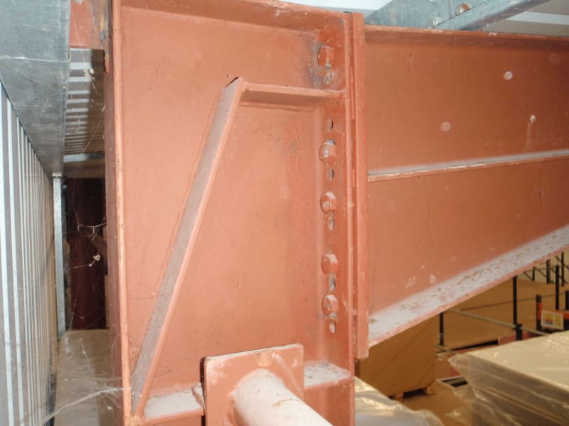
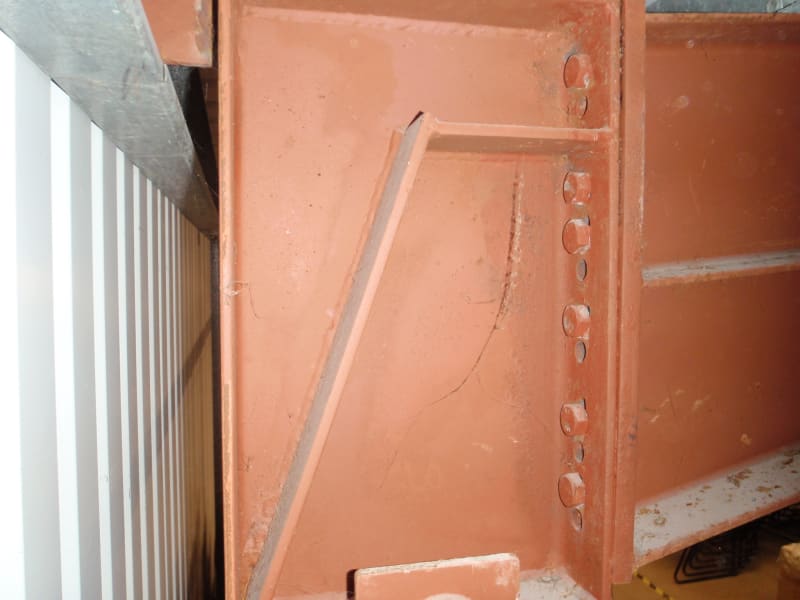
I have an existing portal frame structure i have to check where there appears to have been a mistake in the fabrication of the column / rafter connection, the column flange holes for the bolts were misaligned and new ones were drilled to match the haunch endplate. Many of these additional holes are very close to ones with bolts in, one is right next to it forming a sort of slot hole.
The major design criteria of the flanges is the bending resistance against bolt tension, which is designed by calculating the yield line pattern of failure. These patterns are standardised in Eurocode and I have found that these yield line patterns will clash with the holes closest to the bolts. Can i simply adjust the yield line to miss out the hole, or would assuming a free edge at the edge of the hole be more reasonable?
I have thought of using plug welds to reform the flange - there is no clause for the design of plug welds in bending but i would have thought it would be similar to a butt weld in bending? Though this solution would mean the connections would have to be disassembled in order to no weld the endplate to the flange though so it is not a great option.
Alternatively stiffeners could be installed across the hole, would this be a reasonable solution?
Thanks


