Continue to Site

Eng-Tips is the largest engineering community on the Internet

Intelligent Work Forums for Engineering Professionals

  • Congratulations KootK on being selected by the Eng-Tips community for having the most helpful posts in the forums last week. Way to Go!

Design of slab with opening 2

Status
Not open for further replies.

t230917

Structural
Apr 24, 2019
51
I am designing a top slab for a junction chamber. The junction chamber consists of connecting 2 ends of a 10 feet wide x 4 feet high concrete box culvert.

As part of this design, the top slab has an opening for a 4 foot diameter manhole. The top slab is 1'-1" thick. The manhole is ~10 feet high and weights 8,900 lbs. Apart from the manhole, the slab will be supporting 10 feet of soil (unit weight 120 pcf).

How can I design the top slab? What assumptions do I need to make?
 
Replies continue below

Recommended for you

Seems like a FEA solution is in order.

Is the slab just for the junction box itself?
 
Unfortunately, I do not have a FEA software that I can use. So this needs to be hand calculated.

Yes, it for just the top of the junction box.
 
Place physical beams around the opening, or strengthen the slab locally as embedded beams around the opening. Is this junction box under roadway? What is the maximum water table elevation? Surcharge?
 
The junction chamber interior dimensions should be in the range of 12ft length X 12 ft width and the manhole opening should be located at corner or near to side wall .

That is, it is not necessary to consider the opening for the analysis. The common practice, provide reinforcement at four sides of the opening . Calculate the reinforcement area which clashed with the opening and distribute to four sides.

You can use moment coefficients for the design of slabs and side walls.

 
Can you post a sketch of the problem?

Dik
 
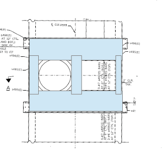
I have posted a sketch below.

OK, I understand. Yes, I designed the slab like a normal two way slab - and the reinforcement that is getting cut out/removed has been redistributed around the opening thru diagonal bars.

No, the junction box is not under roadway. No live load surcharge on it. Water table is below the bottom slab of the junction box.
 
 https://files.engineering.com/getfile.aspx?folder=f737c530-974c-44c8-b931-7a668f795930&file=Annotation_2020-07-26_115602.png
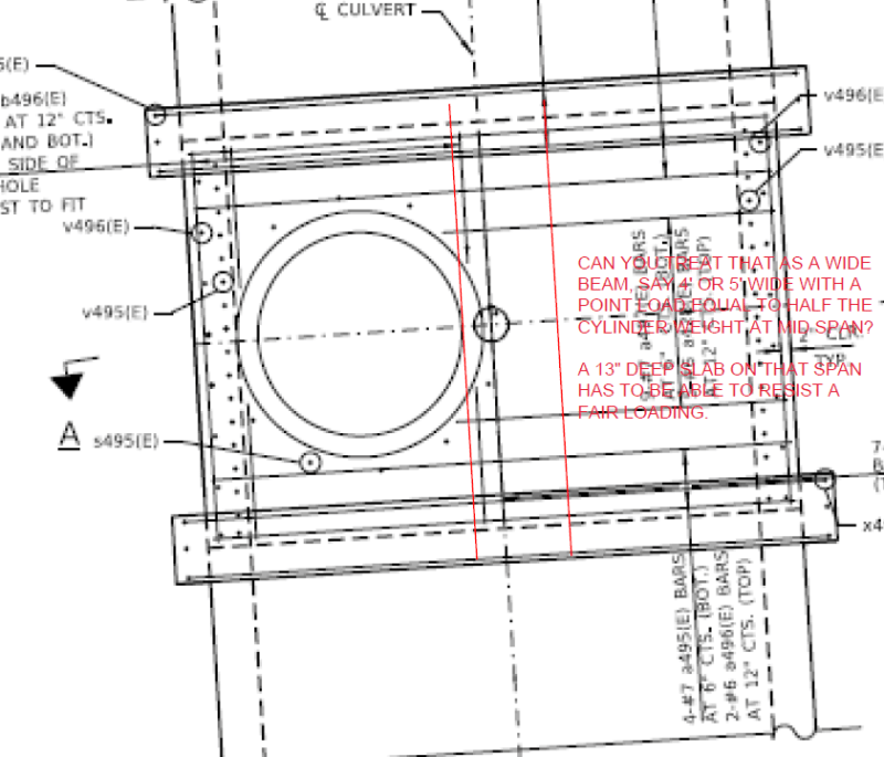
I would design embedded beams, as shown in the sketch below, with minimum /required stirrups.

image_sxb0ym.png
 

But we could not see the redistributed rebars..


The height of the junction chamber 4 ft high.. The purpose of junction chamber for inspection and maintenance. You provided access shaft but the height is not enough. The ht should be in the range of 7 ft. The box culvert implies the line is for storm water .
You may provide a sand trap 3 ft high at the bottom.

I agree with dik (Structural) . You should provide reinforcement at the embedded beam shown with red lines .


I have shown the redistributed bars in the attached PDF.

This is not a typical junction chamber. The main purposed is to attach the riser section on top of it. So in the middle of a run of precast culvert, I have a small 8' section of the cast in place chamber to carry the manhole riser.

I also have separate junction chambers with larger heights.
 
 https://files.engineering.com/getfile.aspx?folder=63f09b2d-ef7e-4aa8-bfa7-12f776e0ccc3&file=Capture.PNG
OK, I can provide an embedded beam as an option here.

How can I check that the slab has enough shear/punching shear capacity for the riser section? The wall of the riser is 5" thick, and it total weight is ~8,000# (1.6 k/ft.)

AASHTO LRFD 5.14.5.3 has a section for this, but I dont know if it applies for a slab with an opening.

Can I just design a 12" strip like a cantilever beam with point load at the end and check if the rebar is good enough?
 
 https://files.engineering.com/getfile.aspx?folder=63f09b2d-ef7e-4aa8-bfa7-12f776e0ccc3&file=Capture.PNG
t230917,
An alternate approach is to extend the structure upwards at the manhole location as shown in the attached document which you can review and tweak. It will give more headroom and better access to the 4 ft high OSHA confined space for several people to work. This will provide better access to do any future concrete repairs. Is the roof cast-in-place or precast? If CIP how do you get forms out?

The displaced soil for 4 ft diameter 10 high at 130 pcf weighs 16328 lbs vs the precast chimney at 8900 lbs.
 
 https://files.engineering.com/getfile.aspx?folder=61aae03f-d3c5-4f58-bce7-223ff77e1506&file=manhole.pdf
Status
Not open for further replies.

Part and Inventory Search

Sponsor