Eng-Tips is the largest engineering community on the Internet

Intelligent Work Forums for Engineering Professionals

  • Congratulations waross on being selected by the Eng-Tips community for having the most helpful posts in the forums last week. Way to Go!

Design of slope Bridge

Status
Not open for further replies.

Vibration Lover

Civil/Environmental
Oct 1, 2018
3
TH
Is there any reasons or Pro &con for design of bridge span not flat?
In case I have to design the elevated like a frame bridge below?
What shall I consider and what shall the dynamic impact factor used?
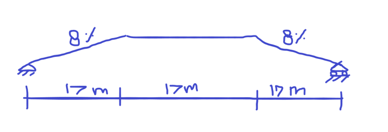
Untitled_p2rfyb.png


Sorry for not a nice sketch
Thanks for sharing
 
Replies continue below

Recommended for you

Usually the slope on the way up is because it is a overpass. But a lot of that portion is typically dirt (i.e. paved road on the ground).

AASHTO has a impact formula.....the trick there would be the "L" to use. It would probably be conservative to use the shortest segment possible. (I.e. 17m.)
 
Usually, a vertical profile like that would be unacceptable to the roadway designers. It would also seem to be more difficult to construct. Why would you not use a vertical curve?
 
Vibration Lover:
It is certainly common to camber the bridge girders for some percentage of their total loading, to compensate for normal deflections due to the various loads. That is HotRod10’s vertical curve. This can be done, or adjusted, by heating on the finished steel girders or rolled shapes. More often, the cambered shape is cut into the girder web and the web fit-up and then the flanges are pressed to the web and welded to it. Prestressed conc. girders are usually cambered by virtue of their prestressing process. This is done to end up with a relatively flat and level bridge under loading, and doesn’t have much effect on the basic design process and approach.
 
Vibration will obviously be worse, as its loaded the supports want to spread due to the presence of the roller support and the 'arch' configuration. For a flat beam there is no spreading effect.
 
"It is certainly common to camber the bridge girders for some percentage of their total loading, to compensate for normal deflections due to the various loads. That is HotRod10’s vertical curve."

Actually, those are separate adjustments. The vertical curve is the final profile of the roadway and bridge. Cambering, slab thickenening, or web cutting is how we get the finished grade of the bridge to match the required final profile after dead load deflections. Web cutting compensates for vertical curvature (if there is any) and all dead load deflections.
 
Structurally, just about anything is possible. However, if you're running trucks on this bridge, 8% is not a desirable grade. Also, check the stopping sight distance.
 
Not sure what the vertical rise in the bridge is, but if your sketch is to scale those "kinked" connections seem like the weak link in the chain. I would envision some pretty large forces and moments, and an overly complicated connection to fabricate and erect (think end plates, stiffeners, CJP welds, etc). The abrupt change in profile does not seem conducive to high traffic volumes or frequent use of the bridge.
 
Motorcity, the "kinks" can be made a couple different ways that are common practice in bridge girder fabrication. It can either be cut into the web of a plate girder, or the kink could easily be made at a bolted field splice.

The question I have is why that profile would be used. It is harder to do, a worse situation for vehicles crossing the bridge, and worse impact on the bridge superstructure.
 
Dear All (WArose,dhengr,Hotrod10, Bridgebuster, Motorcity)

Thank you for your sharing and advice

The reason that have to do this profile is that it has the available limit distance for the approach and we need the clearance height under the bridge. It is still concern us such as;

- What is the dynamic impact factor to be used because we checked the AASHTO which specify 0.33 for girder. But is this enough for cover the impact at the change slope point and how to consider this? Is it like a bump test similar to put the plank in the test bridge.(in such case it seems impact factor will be >0.33 ?). Or we can use the concept advise by WArose.

- As per Agent 666 suggest, we plan to change the support to be pin-pin after put the Steel-Box Girder and casting the concrete pavement.
- We also thinking of pre-camber as HotRod10 instruct.

Thanks if you can share idea .
 
Status
Not open for further replies.

Part and Inventory Search

Sponsor

Back
Top