Continue to Site

Eng-Tips is the largest engineering community on the Internet

Intelligent Work Forums for Engineering Professionals

  • Congratulations GregLocock on being selected by the Eng-Tips community for having the most helpful posts in the forums last week. Way to Go!

Design of the ducts and outlet surfaces

Status
Not open for further replies.

blackarrow90

Civil/Environmental
Feb 19, 2022
6
Hello

I have a question related to the dimensioning of the ducts and outlet surfaces in case of fire. I am not an HVAC but a fire safety engineer and would like to understand the background on how the cross-section of ducts is designed.

Basically, there is a vertical shaft in the building which delivers 7 m3/h of fresh air and goes in the room via a horizontal duct with outlet surfaces (about 10 ft long, see the sketch below). Is it true that the highest velocity in the duct should not exceed 32 ft/s? So I would like to know how wide has to be the horizontal duct in order not to exceed this limit. Should the cross-section of this duct be taken as a relevant surface? In this case, the duct has to be at least 5.8 ft wide, right?
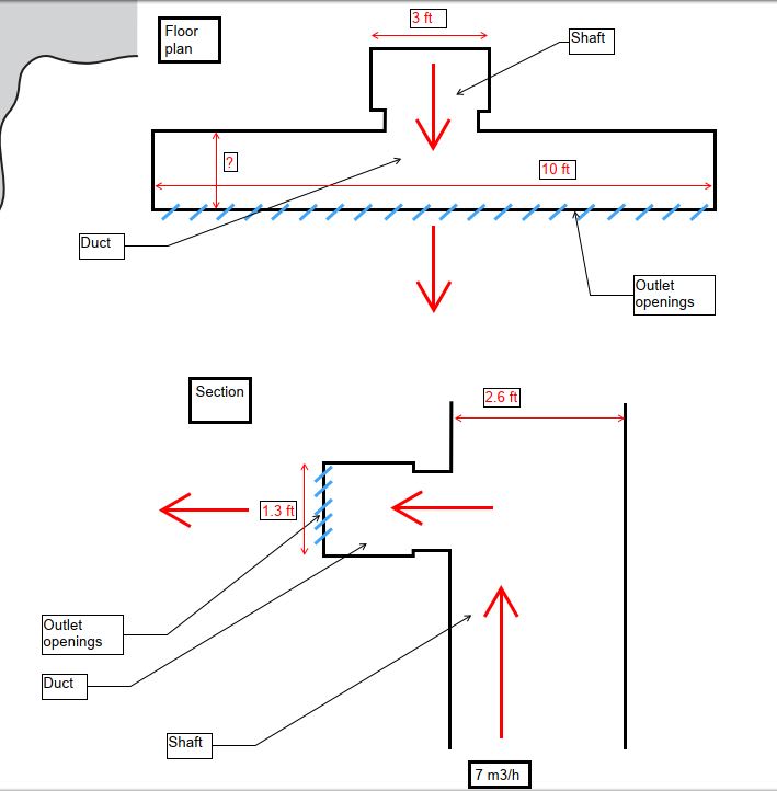
Capture_ldel6i.jpg
 
Replies continue below

Recommended for you

Ducts are designed based on flow rate and limits on a friction rate (often in in-wg/100ft for air in IP), and often a limit on velocity. Those limits depend on the application. Like in an exhaust system that moves particles (i.e. sawdaust) you want a minimum flowrate to not have settlement of particles, but also a maximum to not have abrasion of the duct. In HVAC you also consider noise. Typically larger ducts have higher velocity limits at a given friction rate.

there are online and paper ductulators and charts to find the velocity and pressuredrop for a given flowrate and duct size. Velocity is easy, you can calculate that manually (volumetric flowrate divided by cross-section. but be careful with units). there also are many online resources for recommended velocities. in HVAC I try to stay below 0.08 in-wg/100ft, or at least below 0.1. Some designers may choose cheaper (smaller) ducts and then need a larger fan (with larger power consumption). Rule of thumb means twice the velocity will be 4 times the pressuredrop. So as you decrease ductsize by just a bit, you increase pressure a lot. also note that duct size to cross-sectional area is a square relationship. Going from 10"duct to 8"isn't just 20% more velocity, more like 40% more.

Fire really doesn't play a role in ductsizing. Obviously it plays a role in placing fire dampers. but I'm not aware of a need to size a duct based on the likelihood of a fire unless this is a smoke exhausting system that needs to work during fire. Normal ducts are designed to be shut down in case of a fire (by means or fire and/or smoke dampers and/or shutting of fans)
 
Thank you for the explanation. However, for me it is not clear which cross-section has to be taken into account in the example I mentioned above (the dimension marked with "?" in the sketch). Once the supply air exits the vertical shaft it enters the horizontal duct which goes left and right. So, the air travels with relatively high velocity from the vertical shaft into this "crossroad" and then it spreads into the duct, and through the inlet vents into the room. So, I am not sure if the cross-section is 1.3 ft x "?" or 1.3 ft x 10 ft? For me, it is most important to work with velocities and cross-sections since these are the values that are further important in my smoke extraction/air supply analysis.
 
That looks like a plenum with diffuser. You could have that sized to equal the velocity of the duct. Or much smaller to increase static pressure to get more even flow out over the entire length.

I'd be concerned about the abrupt changes since that causes turbulences and will increase pressuredrop a lot. Always try to have smooth changes in direction or velocity.
 
I agree, probably the worst part of it is the transitions from the duct to the plenum. If my calculation is right, the velocity in the vertical duct (shaft) should be around 32 ft/s. If the plenum is 10 ft long and 1.3 ft high the velocity here will be even lower, around 19 ft/s. I guess these velocities are not posing problems for both the duct and the plenum.
 
You need to have fire damper, access door, and volume dampers to create pressure drop such that the pressure drop here can equal the pressure drop from the main to the worst run of ductwork so flows can be balanced to design values. So fogure on FD w/ AD then Y split and total 4 branches spaced 30" each with volume damper and each connected to the air diffuser plenum. use max 1000 FPM velocity on the plenum.
 
Status
Not open for further replies.

Part and Inventory Search

Sponsor