Continue to Site

Eng-Tips is the largest engineering community on the Internet

Intelligent Work Forums for Engineering Professionals

  • Congratulations SSS148 on being selected by the Eng-Tips community for having the most helpful posts in the forums last week. Way to Go!

Designing footings for wood shear walls

Status
Not open for further replies.

Andy_S

Structural
May 11, 2022
2
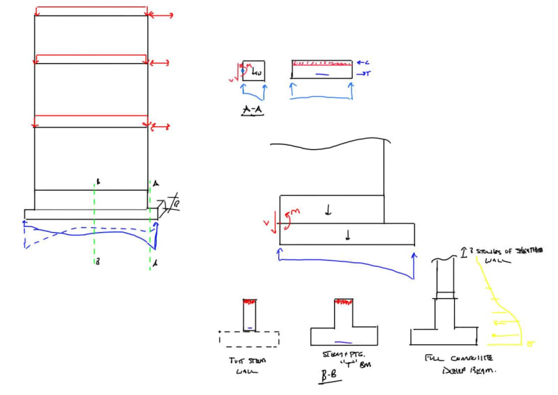
Any input on methodology for designing footings for wood shear walls? Typically I've seen the walls supported by a thickened slab, but is there a way to quantify the width needed for a given soil bearing (assuming it is NOT carrying gravity loads)? Alternatively, if we use spread footings at each end of the wall (for uplift and bearing), can the middle portion of wall just sit on the slab on grade?
 
Replies continue below

Recommended for you

It won't be sized for vertical loads from the lateral shear, but you do need to get the lateral shear into the footing/thickened slab below. So whatever dimensions you need to 1) make the anchor bolt connections along the length of the wall and 2) whatever concrete dimensions/reinforcing are needed to carry that shear to whatever is finally resisting it.

Edit: the above comment is only for the continuous footing along the length. You definitely need footings at each end to handle the chord reactions.
 
See this recent thread where we discussed a similar issues at length: Link

Andy_S said:
Alternatively, if we use spread footings at each end of the wall (for uplift and bearing), can the middle portion of wall just sit on the slab on grade?

1) It is my opinion that, to be consistent with typical shear wall design assumptions, one must provide concentrated foundation capacity beneath the wall chords. And that usually means spread footings at each end or a stiff grade beam below the shear wall.

2) Prefer the shear anchors to be in a slab thickening but I'm okay with them just being anchored into the SOG. At the same time as we assume that the boundary posts of the wall resist all of the overturning, it's a pretty safe bet that the wall studs nearby see some axial load as well.
 
I was going to say that the hold down anchors may be the most important consideration. I would use just the width of the thickened slab, which should be conservative.

You can make an argument that the footing is more of a T or L beam, of course. I won't disagree with that, but I would have to use some rational method to justify the width of the slab included in the T / L beam.
 
Thank you all for the quick responses! Sounds like the boundary elements are what I should be focusing on, and the middle portion of the shear wall footing just needs to be thick/stiff enough to receive the sill plate anchorage and assist with sliding resistance, but not really the overturning couple. I appreciate the help!
 
Andy_S - I'm going to disagree here, while you should focus on the chord forces and overturning, you will get a much better design (less concrete) if you design as a grade beam rather than spread footings each end of the wall.
 
I generally put shear walls on continuous footings and check them like a raft footing with some extension beyond the wall on each side for both stability and bearing pressure. Even though the overturning effect comes out at discrete chord locations in our analysis, the weight of the footing along the wall can be used to resist global overturning of the whole thing. It could be problematic to use SOG weight to resist this as you need to make an assumption of what width is tributary to the wall foundation.

I suspect that if you use only isolated footings at hold down locations you could end up with a pretty large size of footing just to resist the uplift. There are options like using weight of soil above the footing, friction on the shear plane of the soil as well could reasonably used. In my area though it is pretty impractical to bury a big old footing deeper than frost depth for a house shear wall.

Just back of the napkin calc on an HDU8 hold down would need about 5.5' SQ x 2' thick to get enough weight of concrete to resist the holddown uplift alone. Conversely, for compression if you used the same footing you would have like 270 psf bearing pressure. So essentially you end up with a big mass of concrete just to keep overturning factory of safety below 1 and it is not needed for actual bearing on soil. This is why I use cont. footings and their weight as part of the SW foundation system.
 
Aesur - less concrete, yes, but also more steel. Where I am, there's a big difference in cost between the concrete contractors who are capable of installing real reinforced concrete, and the foundation contractors that typically work on houses that through a couple #4's in, pour a footing, and lay 3 courses of CMU. So there's a lot of pressure to keep designs in the 'foundation contractor' wheelhouse and prevent the big markups that come from people who know what they're doing.
 
For the continuous foundation option what are folks opinion on whether to design for considering the bending moment along the length of the shear wall in the foundation or designing for the moment at the face of the stem wall:
Capture1_rar9kn.jpg

Capture2_zmphca.jpg

Capture3_yn3mg7.jpg


I'm making a thing: (It's no Kootware and it will probably break but it's alive!)
 
Celt, I get the ultimate bearing pressure due to the combined loads including overturning, then apply this as an upward pressure on the extension region beyond the shear wall, then proportion the reinforcement based on that.
 
phamENG - good info, you are right it does depend on location; in my area shear walls rarely need extra reinforcing beyond T&S to resist loading, hence why it's more efficient to just use a continuous footing. For what it's worth, I tend to design the footing using an Engineering-International Spreadsheet, EnerCalc Shear Wall module or combined footing module and get great results. I have done some hand checks and compared EnerCalc and Eng-Int and the results are very close which has built my confidence in using such tools.

My area is also experiencing massive concrete (technically it's the cement being rationed so I hear) shortages with contractors being limited to small amounts each week, this is also causing schedules to go bust by months. Because of this, concrete is the controlling aspect over additional reinforcing.
 
Celt83 said:
For the continuous foundation option what are folks opinion on whether to design for considering the bending moment along the length of the shear wall in the foundation or designing for the moment at the face of the stem wall

The grade beam gets designed for the bending along its length. Hence the importance of that member's stiffness in ensuring that the assumed soil stress distribution is achieved.

The strip footing below the grade beam gets designed for the moment at the face of the stem wall.

Are there actually choices available with that? My only decision is whether I'm in the mood for a triangular soil stress profile or a rectangular one.

c01_ohegye.png
 
Section A-A:
Foundation overhang designed for moment at the face of stem wall

Section B-B:
Design as:
just the stem wall
Stem+FTG T Beam
Full Composite Deep Beam

I've seen arguments to hand wave the moment along the wall length because of the deep beam option.

Capture3_sokvb6.jpg


I'm making a thing: (It's no Kootware and it will probably break but it's alive!)
 
Celt said:
For the continuous foundation option what are folks opinion on whether to design for considering the bending moment along the length of the shear wall in the foundation or designing for the moment at the face of the stem wall

If it is a concrete wall above, I just design it for the moment at the face of the stem wall. Belief being that the wall above is stiff enough to prevent much bending from developing in the footing.

For a wood shear wall, I would probably design it for moment along the length of the wall.

Edit: I see with the tiny stem wall, it gets kinda complicated, somewhere in between...

S&T -
 
Celt83 said:
I've seen arguments to hand wave the moment along the wall length because of the deep beam option.

I believe that the "deep beam" approach is a failure to recognize the statics of the situation. Shear walls separate from their foundations at the point of hinging. There simply isn't anything for the foundation below to push up against. This is true at concrete shear walls and, even more so, wood shear walls where the thing you'd be pushing up against is a pathetically shear-flexible wood diaphragm.

c01_opcd7u.png
 
I so badly want to contend with you on this KootK but I can't find a good rationale. The only thing I want to say is that that the location of the pin is the location within the wall where tension flips to compression, for wood walls this is not easily determined.

So then that leaves us with designing our shear wall foundations as grade beams with a simple point load couple at the chords. Next time I'm looking at one of these I will put some numbers to it, but that seems awfully conservative to me. I am interested to see if for a typical building shear wall and stemwall foundation we need anything more than T&S reinf.
 
The statics of the situation requires shear transfer across your rocked up joint, similar to what is required across a flexural crack in concrete. The hold down is there to hold down the wall, at max hold down capacity the elongation of the anchor is 0.107" so your intermittent fastening along the bottom plate handles the shear and some margin of bending caused by the separation.

Capture3_a7zuly.jpg


@driftLimiter:
Here is a spreadsheet I started work on that computes the envelope of moments along the length of the foundation. I stopped working on it pretty much because of this issue as I've yet to proof either direction for myself. Note the spreadsheet relies on macros pretty heavily to handle the shear and moment generation. It's a rigid base approach, you probably should really look at is as a beam on springs.
Link


I'm making a thing: (It's no Kootware and it will probably break but it's alive!)
 
Celt83 said:
The statics of the situation requires shear transfer across your rocked up joint, similar to what is required across a flexural crack in concrete. The hold down is there to hold down the wall, at max hold down capacity the elongation of the anchor is 0.107" so your intermittent fastening along the bottom plate handles the shear and some margin of bending caused by the separation.

1) I certainly agree with the nuances of the shear transfer situation that you've described. At the same time, I don't see how any of that is germane to the question of whether or not the foundation can be considered to be flexurally braced by the wall above. Can you elaborate?

2) I also do not feel that the perceived "smallness" of the tension side separation is relevant. The fundamental nature of a shear wall flexural joint is that the portions of the wall on either side of that joint predominantly tend to pull away from one another. Consequently, they cannot simultaneously push into one another as the "deep beam" approach would seem to imply. This is just as true for a joint separation of half a picometer as it is for a joint separation of sixteen astronomical units.

Celt83 said:
I stopped working on it pretty much because of this issue as I've yet to proof either direction for myself.

Great. Let's get past this deep beam business here and now and turn that spreadsheet into a Celtware app.
 
driftlimiter said:
The only thing I want to say is that that the location of the pin is the location within the wall where tension flips to compression, for wood walls this is not easily determined.

In real life the location of the flip is difficult to determine as you say. No doubt there are s a group of studs in compression at the end of a shear wall rather than just the one boundary post.

That said, when we design our shear walls using the standard "shear panel" assumption, we exploit the maximum lever arm available in establishing our boundary member forces. As such, I'm sure that you'll agree that it would be logically inconsistent -- and a violation of equilibrium -- to then assume a shorter lever arm (distributed axial stress profile) for the design of the foundation.

One could exploit the non-zero width of the flexural compression zone to the benefit of the foundation so long as they also told that same story in the design of the shear wall above where that story be punitive rather than expeditious.
 
driftlimiter said:
Next time I'm looking at one of these I will put some numbers to it, but that seems awfully conservative to me.

It potentially gets much worse depending, partially, on the story that one tells about how shear is resisted.

Where I've practiced, the "grade beam" is usually of an identical cross section to the wall above, as shown in green below. When this is the case, I struggle to convince myself that I'm sure that the governing flexural crack doesn't occur at the top of the footing rather that at the top of the grade beam. And, if that happens, you're left with a very challenging situation with regard to the design of the footing, particularly with respect to shear.

A few times now, I've seen this situation discussed in seismic literature where the grade beam looks a lot more grade beamy, like I've shown in blue below. I sometimes wonder if this is why. This also leads me to wonder if a lot of these situations might be best treated as rocking shear walls rather than shear walls that are truly OT restrained.

C01_cuo1v4.png
 
Status
Not open for further replies.

Part and Inventory Search

Sponsor