Continue to Site

Eng-Tips is the largest engineering community on the Internet

Intelligent Work Forums for Engineering Professionals

  • Congratulations cowski on being selected by the Eng-Tips community for having the most helpful posts in the forums last week. Way to Go!

Designing Foundations with Grade / Tie Beams to Resist Overturning

Philip.screw

Structural
Jan 4, 2024
8
Hello all,

I have had a number of design projects recently where I have had to design foundation to resist significant overturning forces from moment frames.

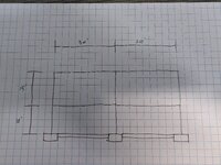
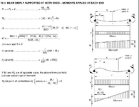
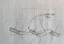
While trying to design the footings for the lateral resisting members, I was running into an issue where my software (RisaFoundation and Enercalc) would report the resultant forces are off the footing and would require footings greater than 12'x12' for it to calculate the bearing pressures. I asked my manager, who is a PE, if they had any advice to resisting the overturning. They suggested using grade / tie beams between the footings which they said would completely resist the overturning forces. Their reasoning is that the grade beam would act like a concrete beam with fixed end conditions.

I'm having trouble understanding how the grade beam can resist all the overturning moment. I've tried modeling footings and grade beams as a matt slab, and I can see how it is providing some restraint. However, I don't think it is right to assume the grade beam completely resists overturning. From my matt slab model, I can see that the "footing" is rotating and not acting like a true fixed end condition. I believe this would make my grade beam to have a pinned end condition instead. Because of this, my footing is not acting like a true fixed condition and is allowed to rotate.

I'm curious to know if it is common to assume grade beams resist all overturning forces or if there are other design methods.

Thanks!
 
Replies continue below

Recommended for you

Draw a free body diagram of your moment frame and share.

You should always do a simple hand sketch when trying to figure things out and not be completely reliant on computer programs.
 
A few thoughts.

If you have such significant overturning moments, you likely have fixed bases for your moment frames. Are you able to get the moment frame to work with pinned bases without drift issues in the frame?

For tie beams, also known as strap footings, the total moment on the system is distributed between the two spread footings at each end. There can be significant shear and moment in the tie beam, but it is an effective way to avoid large footings. I don't have any good examples for this outside of some SE exam prep books.
 
You have two options, a tie beam or a grade beam.

Tie beam provides a tension-compression force and greatly reduces the eccentricity on a footing.
The grade beam actually provides rotational stiffness via flexure and resist the moment that way.

Here is an example FBD for a tie beam. Then its just a matter of statics to determine the moment at the footing base, and tie force required.

If the shear loads are reversible then tipping point A and B need to be evaluated for overturning resistance....

1745948031706.png
 
Draw a free body diagram of your moment frame and share.

You should always do a simple hand sketch when trying to figure things out and not be completely reliant on computer programs.
I've attached a sketch of my frame. I have 3 frames like this in each direction. I'm using fixed bases due to a 2% drift limit. The way it was explained to me was the grade beams will act like the beam in the attach screenshot. However, I don't understand how that is removing all overturning.

I'll definitely make a free body diagram of this, but intuitively if I have moments at the end of my beam, then I must have some rotation as well. And that rotation would create overturning forces.
 

Attachments

  • PXL_20250429_173942792.MP.jpg
    PXL_20250429_173942792.MP.jpg
    4.1 MB · Views: 26
  • tmp_0dc56096-36c3-4451-9dcb-a21d2929a0fb.png
    tmp_0dc56096-36c3-4451-9dcb-a21d2929a0fb.png
    83.5 KB · Views: 26
A few thoughts.

If you have such significant overturning moments, you likely have fixed bases for your moment frames. Are you able to get the moment frame to work with pinned bases without drift issues in the frame?

For tie beams, also known as strap footings, the total moment on the system is distributed between the two spread footings at each end. There can be significant shear and moment in the tie beam, but it is an effective way to avoid large footings. I don't have any good examples for this outside of some SE exam prep books.
Unfortunately pinned bases will not work due to high seismic loads and my risk category making my drift limit 2%. I already have some big column sizes so bigger steel is not an option either.
 
It doesnt remove all overturning. It greatly increases the lever arm of of the overturning resistance.
 
You have two options, a tie beam or a grade beam.

Tie beam provides a tension-compression force and greatly reduces the eccentricity on a footing.
The grade beam actually provides rotational stiffness via flexure and resist the moment that way.

Here is an example FBD for a tie beam. Then its just a matter of statics to determine the moment at the footing base, and tie force required.

If the shear loads are reversible then tipping point A and B need to be evaluated for overturning resistance....

View attachment 8842
It sounds like my manager is talking about a grade beam like you say above. I guess my confusion or lack of understanding is how the grade beam stops all overturning in a footing. Ignoring small rotations and deflections, I do not understand how a grade beam with fixed end conditions between two moment frame footings means there is no overturning moment.
 
There still are overturning moments, but they are resisted not by one individual spread footing, but rather a much larger footing, so the overturning stability issue that you were having would typically go away.
 
You would need to develop the grade beam reinforcement into the footing that is being restrained.

The weight of the grade beam, and any other loads on it push it down, and the soil resists in the upward direction.

If you had a 36" x 24" grade beam with top and bottom reinforcement, it is very stiff against rotation and can distribute the applied bending moment to other footings or soil.
 
Here is a simplified illustration to demonstrate.

The case 3 is a traditional strap beam where you intentionally free the strap from soil so it has only moment and shear in it. Can be done with foam or un consolidated fill.
1000004239.jpg
 
driftlimiter's Case 3 is correctly describing what your supervisor is suggesting - but you need to be careful because the two footings under each column, and the grade beam between them, aren't infinitely stiff and when the frame tries to rotate and lift the back footing upward, the grade beam will be a resisting element but will certainly bend and peel with the uplift.

The amount of uplift resistance you gain with the grade beam tie between the footings depends on the stiffness relative to the geometry and loading.
 

Attachments

  • ET Sketch.jpg
    ET Sketch.jpg
    477.9 KB · Views: 24
Similar to the grade beam ties between isolated spread foundations, you could just use a combined footing under the entire frame. Generally it will allow you to use a narrower footing than spread footings, but the length spans the whole frame. It's probably more concrete than the grade beam ties, but easier to analyze and I think Enercalc even has a calc module for it.
 
Similar to the grade beam ties between isolated spread foundations, you could just use a combined footing under the entire frame. Generally it will allow you to use a narrower footing than spread footings, but the length spans the whole frame. It's probably more concrete than the grade beam ties, but easier to analyze and I think Enercalc even has a calc module for it.

I find it doubtful that you could make the strip stiff enough to treat as a combined footing (rigid body assumption). I would be more open to a beam on elastic foundation.
 
I find it doubtful that you could make the strip stiff enough to treat as a combined footing (rigid body assumption). I would be more open to a beam on elastic foundation.
Looking back at the OP's sketch, yes.......50+ feet would probably be tough to make stiff enough.

The beam on elastic footing approach will yield the same shape as combined footing (rectangular), and again probably easier to find a calculation module for.
 
driftlimiter's Case 3 is correctly describing what your supervisor is suggesting - but you need to be careful because the two footings under each column, and the grade beam between them, aren't infinitely stiff and when the frame tries to rotate and lift the back footing upward, the grade beam will be a resisting element but will certainly bend and peel with the uplift.

The amount of uplift resistance you gain with the grade beam tie between the footings depends on the stiffness relative to the geometry and loading.
So the grade beams provide overturning resistance and prevent the individual footings from overturning, correct? However, there would still be rotation in the footings, and that rotation would depend on my grade beam stiffness. From my FEM matt slab in Risa, I can see that the soil bearing pressure is greater on one side of the footings which I believe is coming from that rotation. Should that be expected and would stiffer grade beams help reduce that? 1745959878904.png1745959846670.png
 
Yes the stiffer you make the grade beam the less rotation at each footing you should see.
If it was infinitely stiff you would see rigid body rotation of all three footings that is a function of the loads and the spring stiffness assigned to the soil.
 

Part and Inventory Search

Sponsor