Eng-Tips is the largest engineering community on the Internet

Intelligent Work Forums for Engineering Professionals

DESIGNING REDUCERS USING ASME VIII DIV 1 2

Status
Not open for further replies.

e1994c

Petroleum
Nov 5, 2019
2
0
0
US
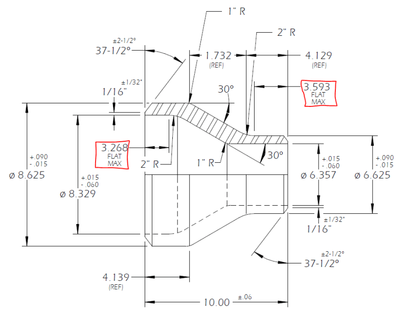
I am a cad designer trying to figure out how to find the following dimensions boxed in red.
I understand they must follow the ASME VIII pressure code but I can't seem to find how to get those dims.

Any help would be greatly appreciated..


reducer_zen7vf.png
 
Replies continue below

Recommended for you

e1994c, a person wonders why you are not just buying a standard fitting, but...

If designed to Sec VIII, Div 1 you will have to follow the rules of UG-36(e) and Appendix 1-5 for internal pressure and, if applicable, UG-36(f) / UG-33(f) and Appendix 1-8 for external pressure.

If your cone-cylinder junctions are considered as "lines of support" there will be restrictions on the minimum cylinder lengths, if not, there are none.

The forgoing applies to 2017 Ed, 2019 Ed may have different requirements.

Regards,

Mike


The problem with sloppy work is that the supply FAR EXCEEDS the demand

Note: Edits in bold
 
Thank you for pointing me in the right direction, I'll do some more reading.


The reason I am not buying a standard fitting is because I work for a pipe fitting manufacturer, and have been tasked with figuring out how to design reducers as the one I attached. I understand all other dimensions except the ones boxed in red.

I was hoping it would be as simple as plugging in some numbers into a formula to get the max flat dimensions. However, I am starting to see that is probably not the case considering the amount of variables to consider for each case. Given that I'm not an engineer, a visual example or step by step guide would help a lot. But I understand it may not be a simple answer after all.

Thank you once again. I will read through the rules of UG-36 and go from there..
 
I see. Actually my previous post was a little broad, the "line of support" concept is only applied to external pressure cases, for internal pressure only there are two alternates for required reinforcement depending on the minimum cylinder length, see 1-5(d)(1) and 1-5(d)(2) for example. Note that reinforcement may be provided by excess thickness of the elements.

You are correct, it is not simple. Vessel designers generally employ software for these calculations. Also, Div 1 may not be your best choice, I assume fitting designers are not tied to a particluar method, etc.

Best of luck,

Mike

The problem with sloppy work is that the supply FAR EXCEEDS the demand
 
Status
Not open for further replies.
Back
Top