Dear all,
I'm a new member of this forum but I've read some interesting topics in the past and I feel I can learn a lot from experienced members here as I'm a young graduate.
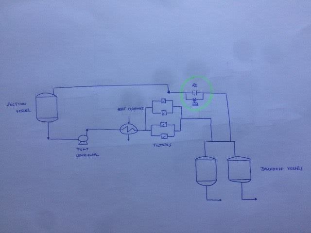
I have a question regarding the design of a restriction orifice in centrifugal pump operation. The function of the RO is to have a continuous minimum flow during operation. In plant designs I've seen, they typically place the orifice in a line going back directly from the pump discharge to the suction vessel. In our system, the line going back to the suction vessel is located much more downstream. The branch is located at the end of the main process line and this main process line consists of piping, fittings (bends, manual valves, check valves) a heat exchanger and filters.
To determine the bore diameter, I need the minimum pump flow (from vendor) and pressure drop. I know the minimum pump flow (16 gpm, the flow through the main process line is 100 gpm) but I'm not sure of how to determine the pressure drop. My way of working is to look at the total differential head at minimum flow (from pump curve) and calculate the suction head. The sum of these two is equal to the discharge head. If I calculate the frictional losses (due to fittings, heat exchanger and filter) and static head, I know which pressure drop the RO needs because the sum of these is the discharge head.
My questions:
- Which pressure drop do I take for the filters? The clean pressure drop or the maximum pressure drop (dirty filters)? If I take the max pressure drop of the filters, my flow through the orifice will be greater when I have a clean filterelement so then my flow through the main process line (100 gpm) will be lower as more flow goes through the orifice. The other way around, If I take the pressure drop of a clean filterelement, then I think there is the risk of going below the minimum pump flow due to saturation of the filter.
- Do I calculate the losses due to fittings, heat exchanger and filters at the flow rate of 116 gpm (sum of both flows)?
- Is it a good idea to have this line so much downstream of pump discharge?
Thanks!
I'm a new member of this forum but I've read some interesting topics in the past and I feel I can learn a lot from experienced members here as I'm a young graduate.
I have a question regarding the design of a restriction orifice in centrifugal pump operation. The function of the RO is to have a continuous minimum flow during operation. In plant designs I've seen, they typically place the orifice in a line going back directly from the pump discharge to the suction vessel. In our system, the line going back to the suction vessel is located much more downstream. The branch is located at the end of the main process line and this main process line consists of piping, fittings (bends, manual valves, check valves) a heat exchanger and filters.
To determine the bore diameter, I need the minimum pump flow (from vendor) and pressure drop. I know the minimum pump flow (16 gpm, the flow through the main process line is 100 gpm) but I'm not sure of how to determine the pressure drop. My way of working is to look at the total differential head at minimum flow (from pump curve) and calculate the suction head. The sum of these two is equal to the discharge head. If I calculate the frictional losses (due to fittings, heat exchanger and filter) and static head, I know which pressure drop the RO needs because the sum of these is the discharge head.
My questions:
- Which pressure drop do I take for the filters? The clean pressure drop or the maximum pressure drop (dirty filters)? If I take the max pressure drop of the filters, my flow through the orifice will be greater when I have a clean filterelement so then my flow through the main process line (100 gpm) will be lower as more flow goes through the orifice. The other way around, If I take the pressure drop of a clean filterelement, then I think there is the risk of going below the minimum pump flow due to saturation of the filter.
- Do I calculate the losses due to fittings, heat exchanger and filters at the flow rate of 116 gpm (sum of both flows)?
- Is it a good idea to have this line so much downstream of pump discharge?
Thanks!