Eng-Tips is the largest engineering community on the Internet

Intelligent Work Forums for Engineering Professionals

  • Congratulations waross on being selected by the Tek-Tips community for having the most helpful posts in the forums last week. Way to Go!

Determine right pressure setpoint 3

Status
Not open for further replies.

saeedplc

Electrical
Nov 27, 2021
126
0
0
IR
Hi dear experts

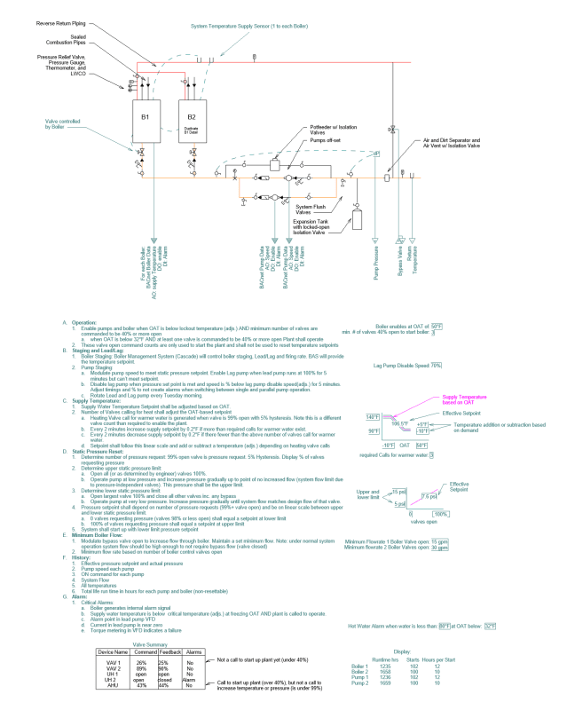
Could you please let me know how to get right diffrential pressure value in secondary loop of chilled water system supplying different terminal units?
A diffrential pressure transmitter has been installed in farthest unit and all units are equipped with pressure independent valves. a Vfd is controlling the secondary pump speed according to the pressure value.
i need to determine right pressure setpoint.
Your reply will be highly appreciated.
 
Replies continue below

Recommended for you

For dynamic reset as energyprofessional stated, I derived its formula from an article discussed on dynamic reset instead OF static fixed setpoint.
Remote loop differential pressure setpoint (dynamic reset)=design loop differential pressure*(current flow/design flow)^2
For example:
Loop design flow rate=2000 gpm
Actual flow rate=1000 gpm
Remote design loop DP=22 PSID
Dynamic set point=22*(1000/2000)^2= 5 psid
See the difference 0f 22 psid at design and it varies TO 5 PSID according to the flow rate
To be honest, I have so far not applied this to my any system. Planning to apply through BMS


The problem with the world is that intelligent people are full of doubts, while stupid ones are full of confidence.
-Charles Bukowski-
 
The problem is, how do you get the 22psi? A design value can be very conservative and may not account for diversity etc. Maybe your design 22psi system in reality only requires 15 psi.

You controls can display a table with all the vale positions and you see what you system is doing and adjust the upper and lower bound base don that.
 
@EnergyProfessional : As you defined in the previous post on variable flow with PICV, finding the maximum pressure and minimum pressure instead of constant setpoint, 22 psid is the maximum setpoint and formula using to finding minimum setpoint instead of assuming 25% of maximum flow when flow is varied. thanks

The problem with the world is that intelligent people are full of doubts, while stupid ones are full of confidence.
-Charles Bukowski-
 
Hi dear experts,

Honestly i thought a lot and reach to this point that:
Constant setpoint method is not applicable for all systems such as those sytems that have very low pressure difference on high and low loads periods.the diffrential pressure transmitter can not be very accurate on very low pressure difference across the low demand terminals.for example in out site the biggest coils of the AHUs take 18 m3 at 0.2 bar however they rarely get to gheir maximum capacity so their pressure drop is even lower and measuring this pressure is not reliable to count on to change the pump speed.
If the system was designed in such a way that with changing the flow of the farthest coil we saw significant change in pressure or at least the pump diffrential pressure using constant setpoint pressure was logical and viable.
In these type of applications the best way for energy saving by changing the pump speed is resorting to pressure setpoint reset by monitoring the critical paths valve positions.
Please have a look at the attached photo that is value of the diffrential pressure of the secondary loop of a chilled system that the pressure transmitter is located 6 meter away the pump. As you can see, the pressure is almost constant in all seasons because the pipe diameters are designed the way that, unit valves opening or closing have no significant influence in the pressure.
For this system i am going to use pressure reset algorithm not constant pressure setpoint.
@EnergyProffessional could you please let me know in detail how to implement the pressure reset algorithm on the system in detail.
There is no huge differdnce between terminal units or coils.

Regards,
 
 https://files.engineering.com/getfile.aspx?folder=334ca2e6-abfb-4536-8ab3-1c8da48a6aca&file=IMG_20220223_163135.jpg
Is the pump single speed, or does it already have a dp sensors and meets a setpoint? If so, of course pressures are the same.
Boiler_jjvfpk.png


See attached boiler plant control sequence with Static pressure reset (under D). See all below for valve summary. Note we also use actuator feedback to verify actual valve position.
 
The pump is connected to a VFD drive and as i mentioned the dp sensor is located some meters away from the pump.
At the time being, the pump speed is not variable and has been limited to 40HZ in the vfd drive and constant speed.
By the way, is there anything wrong in my statement in the previous post?
Altough the pump is running at constant speed but if the load change or demand change we should see pressure change on the dp sensor value because system curve change and consequently intersect in another point on the pump curve but these changes are about 0.02 bar.
Because the curve related to the dp sensor is almost constant i said controlling with constant serpoint pressure is in vain because of the design nature.
In all seasons dp sensor value which is in essence the pump head (discharge pressure minus suction pressure) has a tiny change so dp pressure is always 1.7 bar.
I think by using dp setpoint reset we can change pump speed and see the differences.

Could you please upload a better quality picture.? It can not be read or upload pdf file.🙏
 
Are there 2-way or 3-way valves?

Look at the pump curve, pressure is relatively stable over a range of flow. and if flow increases to some branch, it will decrease somewhat to other branches. You should see some changes, but not really big ones if you have 2-way valves. If you have 3-way valves, flow will be constant, or at least relatively constant regardless of valve position.
 
All the valves are 2 way pressure independent valves(picv)

by considering the dp pressure value do you mean the VFD should react to only 0.02 bar fluctuations?
Something that is very strange for me is that in all seasons even with high and low demands the dp pressure only changed 0.02 bar.
I think by applying the pressure reset method the pump speed will change significantly and power saving would be obvious.do you think so?

Could you please upload a better quality picture of the boiler that you sent before.[thanks]
 
PICV will have the design pressure drop when fully open (often 5 psi - RTFM) and as they close they will increase pressure drop, but reduce flow... which again will reduce pressuredrop back to the design dp. So you won't see a lot of difference on system level.

but even with regualr valves it will be similar. think about it, if the valves are closed, dp will be high, but flow low. if valves are open, flow will be higher, but system dP will be higher.
If you VFD reacts to small pressure changes depends on programming. the VFD itself has a programmed ramp up and down speed to save the rectifiers from wear. and the control algorithm uses some PID loop and delays to avoid quick fluctuations. Everything in HVAC usually reacts slowly since the effects of an action are slow. Like if you heat a room, it heats slowly, the valve doesn't need to close within seconds and so on...
 
Picv pressure drop is depinding on the load and systwm pressure. If we assume the system pressure is constant then pressure across the picv valve is system pressure minus coil pressure ( not consider friction loss). Hope i am correct.
0.02 bar fluctuations are so fast that the system of vfd pid loop will not react to it so the speed of the pump will not changed. however as i said earlier the system are not controlled with the vfd and i am taking help from you to find the best way.
Which control method is better to be implemented in your opinion?
 
@energyprofeesional-the image you posted is not clear. could you please upload its pdf

@saeedplc-measuring dp in kpa is better than in the unit bar.

The problem with the world is that intelligent people are full of doubts, while stupid ones are full of confidence.
-Charles Bukowski-
 
As you see in the curve pressure is accorfing to kpa
But measuring 0.02 bar and vfd reacting to it is impossible. If the vfd react to these fast changing value it will increase decrease speed repeatedly and this type of control is not sensible.
Waiting to hear from you experts.
 
0.02 bar seems to be 0.3 psi. A typical sensor rated to 50 psi max and 2% accuracy would be +/- 1 psi. Most are up to 100 psi or so, so +/- 2 psi. and sensors drift over time and need re-calibration or replacement. With that, the controls contractor likely doesn't worry the VFD every time pressure changes by 0.3 psi.

That's one reason I measure pressure over the pump to get the highest pressure... but that only works with static pressure reset.

You are basically limited by the type of control you want (or don't want) to use, and real-world equipment.
 
Dear EnergyProffessional please dont get me wrong.
As i mentionwd in my previous posts the vfd is not controlling the pump speed and the system is working with constant speed.
I uploaded the diffrential pressure transmitter trend(that is exactly the pump diffrential pressure) in order to get help from you to decide the best way to control the pump speed according to the setpoint reset method. But i am not having enough knowledge of this method to do it and the picture that you have uploaded is not clear to get data from to work out the method.
The transmitter is near the pump and the trend was uploaded so please consider you want to perform the pressure rest algorithm for the system.please let me know what should i do to control the vfd drive according to the dp value that only have 0.02bar fluctuations and very fast.

Thank you so much for your understanding.
 
I don't know how a controls contractor programs that. But I worked out my sequence with the contractor we use all the time and he also stated the newer controllers have the static pressure reset built in, so it isn't like they have to program that from scratch. We use Niagara based controls, which most major brands use. So talk to whoever does your controls on how and what they can do with your hardware.

Older controllers may not be bale to do that easily, or at all. but that would be very old at this point.
 
First off the location of the differential pressure is wrong. The high and low pressure sensor of the DPS are located at the same pressure point so here is no differential. Second you should delete the end of the loop connection because you are just providing a bypass that would negate the use of variable flow control. The first thing you should do is to calculate the required pump pressure and flow requirement. You have to make sure you solve for the worst case pressure drop requirement. If it does show that the worst case is the 3rd branch loop then place the DPS suck that its high pressure port is connected on the main upstream of the branch to the 3rd branch loop. Connect the DPS low pressure port o the main downstream of the 3rd branch loop return. The differential pressure setpoint will be the pressure drop through the piping, fittings, equipment and valves through the 3rd branch loop, between the high and low pressure point of the DPS. I repeat delete the bypass loop at the end of the mains.
 
@lilliput1 :It seems, the end of loop is not a bypass, it depicts the deltaP connection, not piping or bypass looping single DP sensor across the supply and return line. thanks

The problem with the world is that intelligent people are full of doubts, while stupid ones are full of confidence.
-Charles Bukowski-
 
Moideem you are confusing a pressure regulating valve for a differential pressure sensor. The pressure regulating valve is not used to control AFD pumps.
 
@lilliput1 : if you are talking pertaining to the sketch that I sent before, the DPS is in the last terminal unit and also in parralel with it.by the way there is no bypass valve.
All the valves are pressure independent valves. sorry if the photo is not having good quality and cause you make mistake.
 
Ok then if the 3rd loop really turns out to the the run resulting in highest pressure drop then the differential pressure setpoint will be the pressure drop through the piping, fittings, equipment and valves through the 3rd branch loop. For balancing all equipment should have combination flow/balancing valve in addition to the flow control valve and they should have strainer with blow off vale upstream. Also to prevent dead heading the pump the control valve on the most remote units should be 3 way diverting type control valves. Provide enough to be able to pass minimum allowable flow of the pump.
 
Status
Not open for further replies.
Back
Top