Eng-Tips is the largest engineering community on the Internet

Intelligent Work Forums for Engineering Professionals

  • Congratulations waross on being selected by the Tek-Tips community for having the most helpful posts in the forums last week. Way to Go!

Determining amount of air pulled into rail car unloading system 5

Status
Not open for further replies.

Fooooks

Mechanical
Sep 15, 2016
48
0
0
US
Hello all,
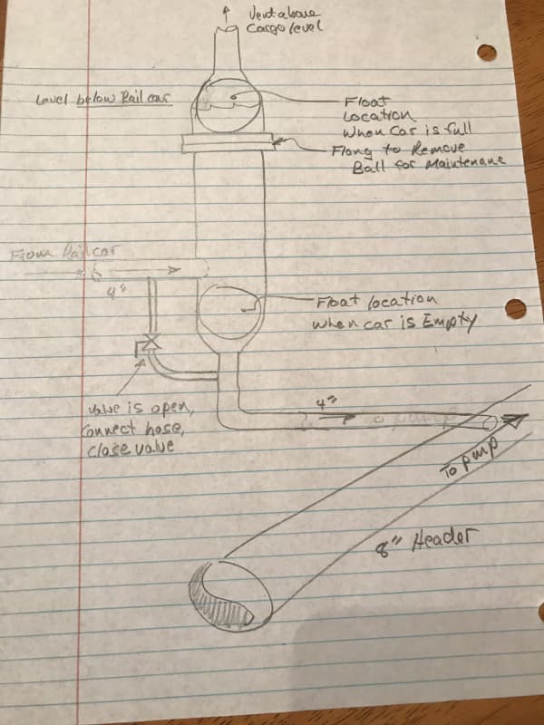
I am having difficulty determining the amount of air that will be pulled into the suction piping when one of our rail cars empties, but the pump is still pumping remaining rail cars. This is the basic scenario:
We are unloading 4 rail cars with a centrifugal pump. When the railcars are full, the pump is producing 1,500 GPM @ approximately 62 ft of head. The railcars go into an 8" header pipe, each using a 4" hose. Naturally, the railcar closest to the pump will drain first; when it does, (if there is no one to close the valve to the unloaded railcar) the pump will continue to run and now pull air into the system. At this point there are 3 railcars with product in them and 1 without product. I am trying to determine the amount of air entering the suction piping from this empty railcar.

I used the same pump and assumed it was just pumping air by itself from the railcar. I used AFT Fathom and it showed that it would pump approx. 1150 GPM of air @ 91.61 ft of head. I have never ran a calculation similar to this before. I do not know how I should go about calculating the amount of air entering this mixed phase system.

Any guidance on this would be greatly appreciated. I need the amount of air entering the system to size an air eliminator on the discharge of the pump.

Thank you kindly.
 
Replies continue below

Recommended for you

if they are all hydraulically connected, than they all will empty at the same rate and none will empty first. this is assuming that they are all on level track and the tanks are all at the same elevation. you shouldn't be drawing air
 
cvg,
From experience, we know that they are drawing air. Also, the cars closer to the pump have less losses in the header and therefore empty at a faster rate than the cars farther from the pump. They share a common header pipe and connect every 70 feet down the line.

We know it is a problem, and now we need to eliminate the air, and are looking for a way to determine the amount of air in the system.

Thanks for the response!
 
Estimate the entrained air volume from the pump discharge pressure or pump flow data. A centrifugal pump cannot pump the air high enough to overcome atmospheric pressure. This will be reflected in lower capacity and discharge pressure. As the percentage of gas by volume increases, the performance of the centrifugal pump decreases. According to the Goulds Pump Manual, a mixture of only 2% gas by volume will cause a 10% drop in capacity. Refer to the chart in the link:

Link

Pumping with entrained air will cause the centrifugal pump to experience a myriad of issues, not to mention maintenance headaches for their operators.
 
once the air is sucked in, your flow rate is reduced and can result in surging or a damaged pump as BIMR indicated.

rather than focusing on eliminating the air on the discharge side, it might be more effective to improve the suction side piping arrangement to increase the capacity and keep the tank levels approximately equalized.

another option (cheaper but maybe less effective) would be to throttle the valves from the two center cars so the flowrates for all 4 are more or less equal.

 
bimr,
Thanks for the response. From your chart, it looks like the pump they tested lost prime at about 10% of entrained air. I could potentially use this as a starting estimate for how much air could be in the line. Assuming that our pump does not lose capacity when air is in the system, and it typically pumps 500 GPM, then we would assume 50 GPM would be air before it loses prime. In reality, it should be less than this if the pump is losing capacity as it draws in air with the liquid, so we should be covered.

It does not give me an exact calculation yet, but it is a good start. And we can also try to monitor pressures/flowrates on the existing pump next time we have a movement into a storage tank. Then we can hopefully determine how much air is being drawn in when a railcar is empty by looking at the decrease in capacity.


Thank you!
 
cvg,
I agree with both of those. Unfortunately this is an old system with no room in the rack to do a piping arrangement change. There are rail spots on either side of the rack, hoses, gangways, a catwalk, and loading arms here. it would be difficult to do so. However, we could throttle the valves to keep the levels equal. The only problem we run into is a shortage of operators, and they have to devote their time to railcars that are being loaded so as to prevent overfill. Therefore, with their priorities, they cannot have someone manning this pump or the unloading railcars at all times.

Regardless, unless someone were there the second the tank car emptied, there would be air drawn into the system, and we do not have the manpower or capabilities of closing the valves to the railcars when the car empties.

We had discussed adding an air eliminator on the suction side, with a level switch and compressor to discharge the air, but it is denatured alcohol and cannot discharge to atmosphere due to our air permit.

Any more input or info would be helpful!
 
What about a permanent restrictor in each line to limit the flow and balance the empty rates.
If you limit the flow rate to what is currently the slowest they should be nearer each other.

= = = = = = = = = = = = = = = = = = = =
P.E. Metallurgy, Plymouth Tube
 
cvg's suggestion seems the best solution at this stage, throttle the inlet flows closest to the pump to reduce their flow rate,possibly a fair bit of trail and error to start with but could result in a reasonable outcome.

It is a capital mistake to theorise before one has data. Insensibly one begins to twist facts to suit theories, instead of theories to suit facts. (Sherlock Holmes - A Scandal in Bohemia.)
 
Sounds like you need something like a float valve inverted. Here is a sketch of a canister that you would put between the 4” rail car hose and 8” header. The canister would have a float in it of appropriate SG less than the product. There would be a valve that would start open to allow the bypass to flood the canister and lift the float. Hook up the rail car and shut the valve, move to the next car to hook up. When the first car empties, the air in the canister allows the float to fall and block the suction.

4D64DF08-47D1-478A-8699-BAEE1853ABE3_prz3bm.jpg


I used to count sand. Now I don't count at all.
 
Wow, SandCounter, that is a superb solution to the problem and more elegant than what I may have suggested. That is far more than a tip; it is free engineering. I hope it is appreciated.

I had decided not to participate in this thread because the problem statement, "Determining amount of air pulled into rail car unloading system", has almost nothing to do with solving the problem. It is actually misleading toward solving the problem.

Fooooks, the first step toward solving a problem is to define the problem. Often, once this is done the solution is obvious or very straight forward. Your first step in this case was off into the weeds. I hope that if you recognize this now, it will help you solve future problems better.
 
There are other solutions available. However, not enough is known about the system or budget to correct the problem.

By adding a pressure tranducer to the suction of the pump, pump controllers like the Goulds PumpSmart may be used to monitor the fluid level in the rail car and can automatically reduce the pump flow and pump speed to avoid the air intake and cavitation problems.

Link
 
Fooooks,

I remember this one and next time it might be better to refer back to it to stop everyone repeating the same things..
To go back to your OP and issue, not withstanding some of the good comments and posts on trying to resolve this issue at source, because you are trying to deal with the effect here and not the cause.

The inlet system at the point where the first railcar connects to the system will be at some pressure less than atmospheric, otherwise the rail car wouldn't completely drain. Now how much below 0barg this is is not easy to calculate as there are many variables.

As air enters the system there is an impact on the pump and outlet head. This will cause your flowrate to lower, which causes the pressure drop in the inlet line to reduce and hence less air or maybe no air enters the system. Thus you can have a surging effect as the cycle repeats.

So how much air? Well I would start with the velocity of the system at full flow and then assume the most air you can get into the pipe before the pump stops working is 15% by volume at a pressure close to atmospheric. Worst case is probably 25%, but then the flowrate will be a lot lower and hence the actual volume of air is lower.

Your issue will be that to work properly, the air eliminator at the inlet to the pump will need to be at less than atmospheric pressure and hence needs a vacuum line, which can get very big.

Your initial calculation is not correct for the pump. Pumps are very good at pumping liquids and very bad at pumping air. Most centrifugal pumps without being made to incorporate it, won't self prime, i.e. if the liquid level is lower than the inlet they won't "suck" the liquid up the pipe, even 1 or 2m.

I would certainly look a little more closely at your system and see if you introduce some form of restriction / orifice plate / partially closed valve on the two tankers nearest to the pump. The ideal would be if the far tanker emptied first as air wouldn't be drawn into the system whilst the rest were still emptying. It might take a little while longer, but maybe open up the last two tankers first then the nearest two later if you can't reduce flow from the first tanker. Try timing the operation so you can see how much faster the first tanker empties, then the second etc so you can see how much flow restriction you need to balance the flows.

Many things you can try, both equipment wise and operational procedures.

Please let us know how it goes - we all really like feedback on ideas posted here and good luck.

LI

Remember - More details = better answers
Also: If you get a response it's polite to respond to it.
 
Edstainless,
Limiting the flow so that they all empty at nearly the same rate is great, but the rail cars could be spotted at various places along the line, and even then, the spots are used with different pumps and header lines. It is not always so that, let's say spot "A" will be for "A" product going to "A" pump through "A" header. There are a total of 20 spots on the track. Also, most of the time the railcars are at the same capacity of product, but there are times when they are not.

Artisi,
Due to the amount of possible unloading spots there are on the track, I do not think this is a great approach, but will continue to look into it.

Sandcounter,
This is a great idea and one I had not thought of. For solving this problem, I had always thought I needed some sort of valve which would detect when there is no flow and then would close. I have dealt with a few vendors discussing this idea, but yours had never come up. This is an excellent idea. The rail cars do vortex as they get lower, and some air would still be entering the system before the railcar empties. Would this cause the ball to prematurely drop, therefor closing this valve? I assume at that point we can open the bypass valve and restart the process. But at least at that point, the pump would no longer be drawing air, which is a huge help. I will continue looking into this and provide an update when I learn more.

Compositepro,
I hope I do not come off defensive in saying this, but the title "Determining amount of air pulled into rail car unloading system" seems to be what I asked for. I was just giving background information on the rail, but ultimately I was just looking for information on how to solve for the amount of air drawn into the suction header. The first replies were discussing drawing in air, then the following replies were trying to fix the problem. Please let me know if I am wrong here, but I was just looking for information to calculate capacity of air.

bimr,
I will ask our Goulds rep about this. I believe we have spoken to him before about the PumpSmart tech. We do have suction pressure transmitter on the rail pumps that connects to our VFDs, however the logic has been improperly set up for a while now and we are working with our VFD vendor to change them all out and rework the logic. It has been a timely process, but this should be able to reduce the speed of the pump based on suction pressure.

LittleInch,
I apologize for not posting the previous thread. That is my mistake. I was trying to separate them so that we can study the amount of air entering the system. There are a few differences: this is denatured ethanol and not a viscous oil, and this is also a centrifugal pump instead of a PD. I will review that thread once more to check for insight. I see what you are saying as air enters, the flow rate will decrease as we move farther right on the pump curve. If I were to find out the maximum % of air before pump failure, I could use that as worst case. The air eliminator, as stated originally, will be on the discharge, which would not require the vacuum line.

I was wondering what you meant by "The ideal would be if the far tanker emptied first as air wouldn't be drawn into the system whilst the rest were still emptying." Why wouldn't the air enter from the farthest car? Would the pressure not be below atmospheric at some point?


One thing I did forget to mention is that we need the vapors to be controlled since this is denatured ethanol. When loading the rail cars, we have a vapor return line which goes to a flair. So I will have to determine how to release vapors to our vapor recovery system and not to atmosphere.


Thank you all for the replies and suggestions. I hope I have answered everyone appropriately so far. Please let me know if you need me to go into any more details on the system.


yeah, probably on reflection not my best comment and more applicable for a gravity fed system into a tank and not a pumped system. But trying to even out the output to get the tankers all going down at the same rate is still a good idea.

I don't think though that an air eliminator after the pump is actually going to do you any good. The issue is air into the pump which is causing loss of flow, not air out. Hence why you really need to have the air drawn out of the fluid on the way in which you then pipe to your flare.

I don't think you'll ever get to a calculation or data on air entering the system as you get into a two phase flow situation with a system and pump only designed for single phase. Two phase flow tends to be unstable and hence there is no right answer. I would still go for 15-20% max air volume relative to full fluid flow and size accordingly, but please think about whether an air eliminator on the discharge will actually do you any good for a normal centrifugal pump.

Remember - More details = better answers
Also: If you get a response it's polite to respond to it.
 
LittleInch,
Thanks again for the response. We will continue to look into it. I cannot believe I did not mention it before, but the reason we originally needed the air eliminator on the discharge is because we are metering the flow into trucks simultaneously. The flow on the pump will be going into one of our storage tanks, while also possible filling a truck at the same time. There is a turbine meter before the product reaches the truck, for custody transfers, and we want to prevent any air from getting to the meter.

There is already a small strainer air release valve before the meter, but with the capability of doing rail simultaneously, we want to avoid any air from entering the meter which may cause inaccuracy or damage.

Thanks again for the estimation on the percentage of air. I will be reaching out to our vendors to see if they can pull information on the pump to tell me the maximum entrained air the pump can handle before locking up.

 
interesting little tidbit. this changes most everything. you cannot measure flow through a turbine meter accurately with air in it, even a little bit. and trying to remove the air in a short run of pipe or hose will not generally be effective. So, as I recommended originally, you need to either eliminate air entrainment altogether (best choice)
or
release the air upstream of the pump (not very effective)
 
This float valve @soundcounter suggests looks a lot like the liquid drainers commonly installed on wet compressed air receivers to drain out water condensate. This also require a level equalising leg from the source vessel which ties in to the drainer body. In theory, this appears to be a great idea for this application, but liquid drainers I've come across are low capacity - high pressure drop, and you need something like 400-500gpm at a low dp for each drainer, so that npsh is not affected, so that is something to check with vendors. Very often, the ball float in these drainers seizes up with corrosion debris / dirt, and plant operators revert to the drainer bypass line, so a y-type strainer upstream of the drainer in this case may also be required. Good to hear you are making progress on the suction line PT / PIC resetting pump speed control loop. If the vapor space pressure in the railcars varies somewhat during the unloading operation, level in the first railcar can only be reliably inferred by dP between railcar bottom drain nozzle and railcar vapor space (since ethanol density is known), so the control loop would then be dPIC resetting pump speed.
 
1 or 2 % of air entering a centrifugal pump will affect performance with something like 6% enough to air-lock the pump, this of course will depend on the pump design and other factors so is a little arbitrary.
There are a number of "tricks" that can be used to assist with air handling but again this depends entirely of the pump design and probably not suited to your particular pumps.

It is a capital mistake to theorise before one has data. Insensibly one begins to twist facts to suit theories, instead of theories to suit facts. (Sherlock Holmes - A Scandal in Bohemia.)
 
Status
Not open for further replies.
Back
Top