Eng-Tips is the largest engineering community on the Internet

Intelligent Work Forums for Engineering Professionals

Determining Maximum Load for Flat Roof for Solar Panel Installation 2

Status
Not open for further replies.

BufordTJustice

Mechanical
May 19, 2004
26
0
0
US
Hello-

I have a flat roof onto which I am interested in installing some solar panel arrays. As I am in a high wind area (design is ~145 mph), I either need to penetrate the roof 50+ times to anchor the panel mounting rails, or use a ballasted system and avoid the penetrations altogether.

I am leaning towards the ballasted approach as it not only eliminates the cost of large number of roof penetrations but also the opportunities for leaks which will certainly become more likely with so many penetrations. The ballasted approach also removes uplift loads from being applied to the roof structure itself (as the ballast is sized accordingly to handle this).

In any case, the specifics of the roof are as follows----

The roof is flat (covered with a single ply TPO membrane over 1/2" iso board, which is over 1/2" plywood sheathing). The trusses are parallel chord type and are spaced 24" OC across the roof and are comprised of 2x4 members. The span between vertical supports is ~12 ft and the depth of the truss (measured between the outside of both the top and bottom chords) is ~68" A photo is below.
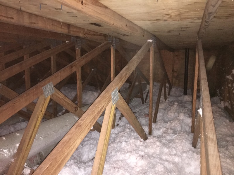
IMG_5830_h5qdvk.jpg
.

Is there an easy way to determine the maximum load in psf this roof could be expected to support? I'm going for permit for the solar system this is going to be question 1 that I have to answer. Thanks for the help!
 
Replies continue below

Recommended for you

All I was trying to get across was that, while most of the discussion here has been about gravity loading, uplift/suction is a major consideration in hurricanes. I am not sure what the uplift load on those panels would be, but think it would be a lot more than 10.5 psf in Tampa.

Saying that you wouldn't be worried about solar panels in a Cat 5 hurricane is not good enough, in my opinion.

I think you need a Florida structural engineer to comment on this. So far, none of us are.
 
Yeah...I shouldn't have joked around about the cat 5 thing. That was inappropriate in a tech discussion. My intent was, in a tongue and cheek fashion, to implicitly recognize that in a cat 5 storm, my house would not be likely to be standing, so the mounting means for the panels would be not matter much at that point.
 
I can't comment on hurricane prone regions. But some solar panel stand manufactures have done wind tunnel testing to justify unbelievable little ballast.
 
Florida guy here....Your uplift pressures should be anywhere between 30-75psf (asd) depending on wind speed, exposure, roof height, zones, ect. but could be higher. Code says the addition or replacement of roofing/equipment shall not increase the force in the elements by more than 5 percent; its also says a second layer of roof covering shall not be more than 3 psf over one existing layer of roof covering. Adding ballast is going to throw you over the this threshold for sure as I believe just the panels are going to be 2-3 psf additional. These panels and supporting rails should have a florida product approval or at least testing data/analysis right? If so there should be allowable wind pressures and fastening schedules on the florida product approval depending on your site criteria. If your site is outside what the products were tested/analyzed for you are going to need to hire an engineer anyways. I would also go down to archives in the city and pull any plans they have on the existing structure to see the design criteria and work backwards from there. If no design information is available or they dont have anything then you would have to go to references or call some local truss guys for some guidance.
 
Thanks for the reply kmart30. As this construction appears to be not something I can look up online in a table, do you have any firms around Tampa Bay that youd know of who could provide an analysis of this roof support to confirm it can hold the designed ballast weight?
 
Im not in the Tampa area but I know of one firm that may be able to help you. I dont think I can mention firm names on here but if you google "tampa site specific engineering" the one I know should be close to the top. Good luck!
 
All-

Im working with a local truss engineer to sturdy up my trusses a bit.

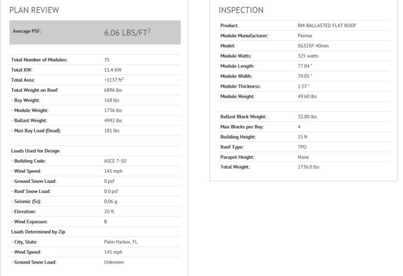
But, it looks like the average load for the ballasted solar mount arrangement is only going to come in at ~6 psf including the panels. What do you guys think of this? Ill of course be digging into this more (apparently Unirac engineers will sign off on this), but at 6 psf its so much less than I originally thought.

Loading_njqsqp.jpg
 
Here are the assumptions for the design. Does anyone see anything here that may not fly with the building department?


RM10 U-BUILDER PRODUCT ASSUMPTIONS

RM10 – Ballasted Flat Roof Systems

Building and System Occupancy/Risk Category II
Building Height ≤ 60 ft.
Roof Slope ≥ 2.4° (1/2:12) and < 5.6° (1-3/16:12)
Friction Tested Roofing Types: EDPM, PVC, TPO, and Mineral Cap
Required Setback from Module Edge to Building Edge for Wind Tunnel: 3 ft
Surrounding Building Grade: Level
Wind Design: Basic Wind Speed Range is 85-150 mph (ASCE 7-05) and 110-170 mph (ASCE 7-10). Wind Exposure: B or C (ASCE 7-05/ASCE 7-10). Occupancy/Risk Category II buildings and systems with a 25 year design life. Insertion of the project at-grade elevation can result in a reduction of wind pressure. If your project is in a special case study region or in an area where wind studies have been performed, please verify with your jurisdiction to ensure that elevation effects have not already been factored into the wind speed. If elevation effects have been included in your wind speed, please select 0 ft.
Ground Snow Load (ASCE 7-05/ASCE 7-10): 0-60 psf. Results are based on uniform snow loading and do not consider unbalanced, drifting, and sliding conditions. Roof snow load reduction calculated per Section 7.3 of ASCE 7 with the following assumptions: Exposure factor = 0.9, Thermal factor = 1.2.
RM10 Ballast Bay Weight: ~3.5 lbs
Module Gaps (E/W) = 0.25 in
Seismic: Installations must be in seismic site class A, B, C, or D as defined in ASCE 7-05/ASCE 7-10
Ballast calculations are based on ASCE 7-05/ASCE 7-10 load combinations and product specific wind tunnel testing.
Ballast Blocks: The installer is responsible for procuring the ballast blocks (Concrete Masonry Units – CMU) and verifying the required minimum weight needed for this design. CMU to comply with ASTM standard specification for concrete roof pavers designation C1491 or C90 with an integral water repellant suitable for the climate it is placed. It is recommended that the blocks are inspected periodically for any signs of degradation. If degradation of the block is observed, the block should immediately be replaced. The CMU ballast block should have nominal dimensions of 4”x8”x16”. The actual block dimensions are 3/8” less than nominal dimensions. Ballast blocks should have weight as specified for the project in the “Inspection” section of this report.
Limitations of Responsibility: It is the user’s responsibility to ensure that inputs are correct for your specific project. Unirac is not the solar, electrical, or building engineer of record and is not responsible for the solar, electrical, or building design for this project.
The system is certified to UL2703 when properly installed. See the installation guide for more detail.

SEAOC PV1-2012: Structural Seismic Requirements and Commentary for Rooftop Soar Photovoltaic Arrays

Assumptions for unattached photovoltaic arrays:

Importance Factor: Array (Ip) = 1.0, Building (Ie) = 1.0
Site Class = D
S = design seismic displacement of the array relative to the roof
Minimum Separation: Array to Array = 0.5*S, Array to Roof Edge or Obstruction with Qualified Parapet = 1.0*S, Array to Roof Edge with Unqualified Parapet = 1.5*S
SS = mapped MCER, 5 percent damped, spectral response acceleration parameter at short periods per ASCE 7-05/ASCE 7-10
SDS = design, 5 percent damped spectral acceleration parameter at short periods per ASCE 7-05/ASCE 7-10
A minimum module return flange of 0.9in (when using 1-3/4 in. clip bolts) is required for all RM10 installations
A minimum module return flange of 0.65in (when using 2 in. clip bolts) is required for all RM10 installations
Coefficient of friction used for calculations per Unirac, Inc. Roof Mount Ballast Support Coefficient of Friction Testing report dated October 4, 2013. Roof pads are required for PVC, TPO, and EDPM roofs to attain a minimum coefficient of friction of 0.4. Mineral cap roofs do not require roof pads to attain a coefficient of 0.4.

 
It is about what I expected...that final responsibility rests with the EOR....meaning that he has to interpret the wind tunnel tests to determine if they are applicable to a particular installation...meaning he takes full responsibility for taking this product from a controlled wind tunnel test and applying it in a real world case....tall order indeed...does anyone know if the codes have weighed in on these yet...
 
SAIL3 has the right handle. As I stated before, I would expect those panels to be blown all all over the countryside. Hope they don't hit anyone.
 
Well, whats cool is that Unirac provides this letter with the design (which likely helps with the EOR concern, as theyve already provided the EOR of sorts). Of course, one still has to look at the structure onto which these mounts are placed.

Letter_kfdwji.jpg
 
Ill have the same calcs coming from another supplier shortly as well......Ill be curious to see if they are similar. Im guessing theyll be more or less the same.
 
Hokie66-

Im not posting here too much about the fact that I am also looking at the mechanically attached approach as well. That method is rather self explanatory and the uplift/downforce info is readily available (so I haven't needed any additional help with it).

As such, Im certainly not locked into the ballasted method, but its the more interesting one to chat about :)

It is looking like it will be less expensive (perhaps by a good margin) to take this route but well see.......
 
Sail-
As I look into this stuff more, Im finding that type of letter is available from all of the manufacturers of these types of mounts (and mechanical ones as well), state by state. I suppose the efforts they've placed onto these systems is not surprising (as the companies who manufacture this stuff are not small entities). Hilti for instance owns Unirac (the manufacturer of the system I posted the calcs on above). They are certainly no newbies when it comes to structural elements.
 
Every city is different; you could be a PE with absolutely no knowledge in what you are doing and all the city looks for is a stamp. If you get a building official/plan reviewer who knows what he is doing he will look past the stamp and look to the code. The further south you go the more strict cities/counties are with wind requirements. This is what the Florida Building code requires for "wind resistance" for PV panels:

1507.17.3 Wind resistance.
Building integrated photovoltaic roofing modules/shingles shall be tested in accordance with procedures and acceptance criteria in ASTM D 3161 or TAS 107. Building integrated photovoltaic roofing modules/shingles shall comply with the classification requirements of Table 1507.2.7.1 for the appropriate maximum basic wind speed. Building integrated photovoltaic roofing modules/shingle packaging shall bear a label to indicate compliance with the procedures in ASTM D 3161 or TAS 107 and the required classification from Table 1507.2.7.1.


Were the panels tested in according to these tests? If not, then as a good building official/plan reviewer I would want testing data, site specific calculations, ect. from a Florida PE that would justify the design is within standard engineering practices and other code requirements. It looks like you have that already from the manufacture and that might be enough for an approval. However, the manufacture is in the business of selling their products and the building official might request a letter, plans, calculations, ect. from an engineer (3rd party, EOR) to further validate the design of the system.

From the EOR's perspective (my opinion), these panels were tested in a wind tunnel based on dead load and friction more than likely in perfect conditions. I would want to see at what pressures these panels/ballasts failed at, the mode of failure, and how they ended up with their allowable wind speed range and other criteria. After this I would need to look at the site specific conditions, apply a hefty safety factor and see if it works or not. There are a lot of variables to think about if you dont have this testing data which is why the code requires specific testing and product approvals.


Status
Not open for further replies.
Back
Top