Hello,
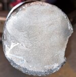
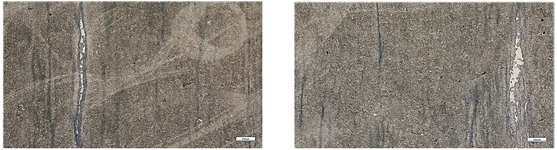
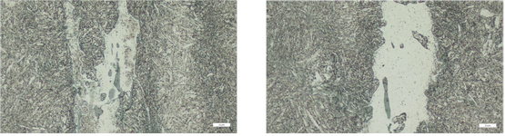
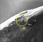
A broken pump shaft made of 1.4021 stainless steel failed at room temperature. The broken surface looks smooth and shiny, with some sparkles when tilted. Under the microscope, the cracks mostly followed the grain boundaries (intergranular fracture), which usually points to brittle fracture. We initially thought the material might have been weakened (e.g., due to bad heat treatment). But mechanical tests don’t back this up: the impact toughness test gave 32 Joules, which is higher than the required value for this steel.
Why it’s likely not fatigue:
No classic fatigue clues like beach marks, ratchet marks, or fine striations on the surface.
Fatigue cracks usually grow through the grains (transgranular), but here the cracks followed the grain boundaries. While rare, intergranular fatigue can happen in special cases (like high heat), but this failed at normal temperatures.
The confusion:
The grain-boundary cracking suggests brittleness, but the material’s impact toughness is good. What’s going on? Please Let me know your thoughts!