Continue to Site

Eng-Tips is the largest engineering community on the Internet

Intelligent Work Forums for Engineering Professionals

  • Congratulations waross on being selected by the Eng-Tips community for having the most helpful posts in the forums last week. Way to Go!

Development Length

Status
Not open for further replies.

dcvo89

Civil/Environmental
Jun 26, 2016
5
Hi,

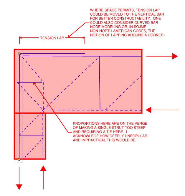
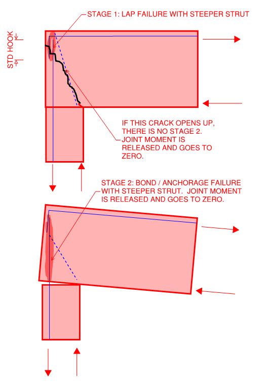
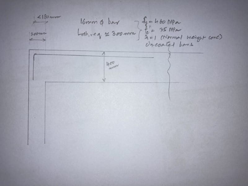
Let's say you have a concrete beam that hangs off the side of a concrete column. For the rebars that extend from the beam and into the column, I need to calculate the development length. Based on the equation for development length (ACI 318-14 Chapter 25: Section 24.4.2.3), there are variables that relate to transverse reinforcement (Atr), tension reinforcement (s and n from the Ktr equation), Cb, and the Psi factor for casting position. Would these be based off of the geometry and reinforcement of the beam or the column?

Also, the development length would just be the length perpendicular to the wall and any hooks (if using the equation for a hooked bar) wouldn't count towards that, correct?

Thanks,

 
Replies continue below

Recommended for you

dcvo89 said:
Would these be based off of the geometry and reinforcement of the beam or the column?

The beam, especially if the beam pour would interrupt the pours of the columns above and below as is typical.

dcvo89 said:
Also, the development length would just be the length perpendicular to the wall and any hooks (if using the equation for a hooked bar) wouldn't count towards that, correct?

Correct.

Keep in mind that what you're talking about here is really a moment frame joint. As such, there's a bit more to it than just development length. I'd recommend picking up a copy of the document below if you don't have one already.

c01_qzbaps.jpg
 
Thanks KootK. If I were able to use the development reduction that is a ratio of the As,req/As,provided, this would also be based on the flexural reinforcement of the beam, correct?

Similarly, if I have a retaining wall where the vertical reinforcement of the stem gets embedded into the footing, everything would be based off of the stem (including that development reduction factor)?

I'll look into that document, thanks.
 
Yup, the As ratio pertains to whatever bar is being developed.
 
Thanks KootK. So basically the member that receives the incoming development length doesn't really have an effect on development length except the available embed that it can provide (such as width of a wall) and whether or not a hook is required.

Have a great rest of your weekend!
 
Keep in mind as well that the transverse reinforcement reduction for development length only applies if there are orthogonal stirrup sets around the bar being developed. So in a beam column joint this does not apply as the joint reinforcement is typically around the column bars, parallel to the beam bars being anchored.
 
Thanks Agent666. Let's say I have a concrete beam that sits on top of a retaining wall. The concrete beam has stirrups and I continue the longitudinal reinforcement of the beam and embed it into the top of the concrete wall. Could I use that traverse reinforcement (stirrups in the beam) to reduce the development length going into the wall?
 
If the stirrups continue to the end of the hook, and they meet any minimum spacing and number, then yes I believe you can take that reduction.
 
I am not sure I completely understand this discussion, but keep in mind you must develop reinforcing on BOTH sides of any critical plane of failure. Therefore, any beam reinforcing must be developed within the beam AND within the column (usually by hooks). The reinforcing in the column is generally not a problem, because it will be continuous both above and below the beam. The special case for a beam at an uppermost story, where the column does not continue above the beam, requires special attention, to develop the reinforcing within the column.

DaveAtkins
 
Dear all, regarding the same topic and discussion, I would also like you all to answer some of my queries.
Please check the picture attached. There is a common practice to connect 400-800mm deep beams to columns having a width of 200mm(in the area I work). As calculated through ACI code, the hook development length required after considering all factors comes out around 300mm which is clearly not available. However, all the connections are considered as rigid/fixed during the design stage. Is this acceptable? What are other solutions to this as width of columns are always kept 200mm(width of wall)..
IMG_7581_q6e3et.jpg

Also, what should be the details of slab extra top rebar at top of the columns? They should be bent into the columns for fixity?
P.S: Assume the bars to be fully stressed.
 
MSUK90,

For your first question, bend column outer bars, or provide L bars, into the beam, and splice to the top beam bars with tension splice length. However, I don't think the "column" is sized adequately to provide full restrain of the beam.
I don't understand your second question. What is the extra bar? If you want to extend this discussion, please open a new thread with additional sketches.
 
In my opinion, the hooked bars are not fully developed, and you cannot assume full fixity at the end of the beam. I would use a reduced fixity which correlates to the reduced development length.

Now...regarding bending column bars into the beam and splicing them with the beam top bars to achieve full fixity, I have never been comfortable with that approach.

But I know someone who might be able to shed light on this. Is it a bird? Is it a plane? No, it is KootK[wink]

DaveAtkins
 
The dowel into the beam and splice suggestion is based on the assumption that due circumstance, no change is allowed. Otherwise, there are many ways to handle this situation - increase column size, add bull leg, reduce beam span (meaning adding another beam maybe). Do not try partial restraint, without change the load intensity, or rearrange the structural elements, the force likely will be there to pull the bars straight.
 
What does it look like to consider partial fixity (assuming that goes beyond the limits of moment redistribution provisions)?

----
just call me Lo.
 
MSUK90 (Structural)

I may have misunderstood your problem but I do have the following observations:-

If you assume the 400mm deep beam to fail at the inner vertical face of the wall the development length will have 3 sections for the top rebar. First would be the <180mm horizontal section you have marked up. The second is the right angle hook worth about 8 times the bar diameter and lastly the vertical section which I estimate according to your drawing to be <380mm. Therefore theoretically the development length = 180mm+8x16mm+380mm = 688mm which is 43 times of the diameter. As a rule of thumber a lap of about 42 times the diameter is normally enough to develop the full material strength of a high yield bar. Thus the design is satifactory as long as provision of the development length.

However in the above assumption the failure plane occurs vertically. By inspection your design will fail at a horizontal plane at the bottom level of the 400mm beam. This is because (1) The 400mm beam is 8 times more stiffer than the 200mm wall (per unit width as second moment of area is proportional to the cube of the height) so the wall will break first and (2) your diagram shows no reinforcement between the beam and the wall if the two separate horizontally at the beam's bottom line.

MY guess is you would have some wall reinforcement extended vertically but not horizontally into the body of the 400m beam but the failure would still occur. You may not see it easily as avaialble vertical reinforcement could hold the beam in position. The dead weight of the beam compresses the failing horizontal surface. In such a case if you can accept the cracking, which may not be very much, you have effectively achieved the design by simply supported condition in practice even if you have assumed the node is rigid theoretically.

If you want the wall to be rigid with the beam you need to extend the vertical section of your existing bar by about 42 times the diameter below the bottom level of the 400mm beam.

The 42 times the bar diameter for developing full material tensile stress is just a rule of thumb but it is a good practise to have it as the minimum and then followed by the ACI codes. The rules of thumb are given at least in the earlier versions of Reinforced Concrete Designer's Handbook by CT Reynolds and JC Steedman.
 
DaveAtkins said:
Is it a bird? Is it a plane? No, it is KootK

YES!!!! I've been wanting to chime on this super bad but have been holding back because I didn't want to contribute to feeding the animals so to speak with respect to thread hijacking. But, now that you've invited me across the threshold...

1) With respect to the design of the beam, at these proportions I would always design the beam ignoring joint rigidity altogether. For detailing and crack control purposes, I'd install some hooked bars equivalent to at least 25% of the bottom steel area and extend those out to around 30% of the span length.

2) Were I to attempt to make this connection an ideal, rigid joint, I'd take the approach shown in the sketch below. Nobody's going to want to build that.

3) In my opinion, unless there's a column on top of the joint to provide a kick-ass clamping mechanism, I would not be calling this a rigid joint unless bar continuity was maintained around the outside corner somehow.

4) With a column on top, and full bar development into the joint, I would support calling this a rigid joint.

5) With a column on top, and partial bar development into the joint, I would not support calling this a rigid joint, even with the moment transfer capped at the moment corresponding to the tension capacity of the partially developed flexural bars. My reasoning for this stance is that the bar tension will continue to grow until one of these things happens:

a) The bar yields which can only happen with full development or;

b) The bar tears out from the joint in an anchorage / bond stress failure which is obviously unacceptable.

c) A concrete strut or shear failure occurs someplace, the timing of which cannot be predicted accurately.

In my opinion, partial bar development is the domain of situations in which the bar tension demand is self limiting to a value less than fy. I feel that it is erroneous to use partial development as a means to limit bar tension / joint moment supply.

6) Because of #5, I feel that moment redistribution and partial bar development are fundamentally incompatible. That said, I violate the code prescribed limits on moment redistribution all over the place. I'm also confident that everybody else does too whether they are cognizant of it or not.

c01_mzqznj.jpg
 
This is what I feel the most likely failure progression would be for one of these joints constructed in what I would consider the most probable way.

c01_btu4pp.jpg
 
The tie is a good idea, it can be tied to the column inner vertical bars, which will pass beyond the bottom of beam.
 
saikee119 said:
Therefore theoretically the development length = 180mm+8x16mm+380mm = 688mm which is 43 times of the diameter
.

I disagree. That is not how development works. The ACI Code allows for straight bar development, or hooked bar development, but not adding various lengths together.

DaveAtkins
 
It's not how it works in ACI. Or CSA (Canada). Some countries do develop around corners though.
 
Status
Not open for further replies.

Part and Inventory Search

Sponsor