Eng-Tips is the largest engineering community on the Internet

Intelligent Work Forums for Engineering Professionals

[DG SET] What is the difference between DG Crank & DG Run relay? 3

Status
Not open for further replies.

Rejeckted

Electrical
Mar 7, 2021
37
0
0
IN
Capture_yuzbvb.png


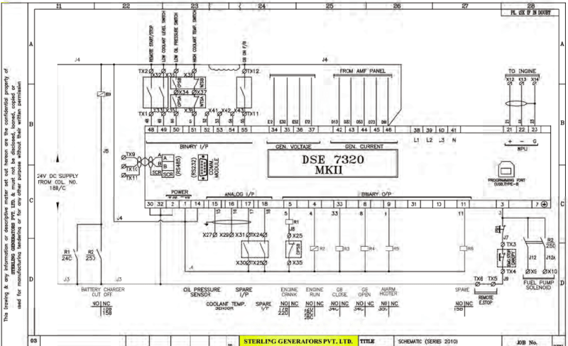
This is an scheme of LCP (Local Control Panel) in DG SET. Here the controller gets input from AMF panel. I was just wondering what is difference between DG Crank & DG Run relay R1 & R2 (just asking in general about the sequence of operation).

As I have read a DC supply from battery needs to give command to starter motor (DC) through solenoid coil. This cranks the crank shaft & starts the combustion/ expansion piston process. So what is the DG Run/ DG Crank relay for? Does it have to do with Fuel Inlet?

Also in the given scheme the controller gives o/p 24V to the relays. But what if an emergency situation & controller fails to give command, is there a possibility to loop & provide direct 24V to relay?

Best!
 
Replies continue below

Recommended for you

All numbers are common examples and not specific to your application.

For electronic engines, DSE run relay energizes the engine ECM and signals it to be in the "run" state.

The DSE start relay energizes the the stater solenoid to crank the engine.

Once the ECM sees a certain RPM, fuel injection starts (300 rpm or so for highspeed engines).

Once the crank terminate speed is exceeded, the DSE controller opens the start relay (~50rpm above injection speed).

If the DSE controller does not see crank terminate speed after a set time interval it will go into an overcrank fault (~30 seconds)

For mechanical engines the run relay controls the injection pump shutdown solenoid. For mechanical engines with hydraulic governors, the run relay controls the solenoid valve on the spill port for the power piston.
 
Thanks for your reply.

So as I understand, the crank relay initially cranks the engine with the help of starter motor. Once certain speed (say 300RPM) is reached this relay de-energizes. At the same time, the engine goes into run state now and hence energizes the run relay that initiates the fuel injection to increase the speed from 300RPM to 1500RPM. The engine keeps running till the fuel injection is ON. Once we give stop command to Disel Generator, the Run relay de-energize & the fuel injection solenoid de-energize shutting down the mechanical process & gradually reduce the speed.

Am I correct here?

Best!
 
Once certain speed (say 300RPM) is reached this relay de-energizes. At the same time, the engine goes into run state now and hence energizes the run relay that initiates the fuel injection to increase the speed from 300RPM to 1500RPM.
Not quite.
1. Start relay energizes starter.
2. Run relay energizes ECM in run mode.
3. At 300 RPM, ECM starts fuel injection.
4. At 350 RPM, ECM assumes engine has started and terminates cranking. (De-energizes start relay.)
Subject to review by Tug.

--------------------
Ohm's law
Not just a good idea;
It's the LAW!
 
For clarity, ECM = engine control module, the computer that the engine manufacturer supplied.

DSE = Deep Sea Electronics, the generator controller.

The corrections would be that the ECM is energized set to run by the DSE prior to energizing the start relay. The DSE terminates the start sequence.

If you aren't using a controller most engine ECM's can do the start run stop sequence on their own but it simplifies the setup to do it in the DSE controller which is much more user-friendly to integrate into control systems and program.
 
To expand on the responses here, there's a couple of options on what is happening, and it depends on the specific configuration.
Run relay is generally a permissive to run, as both waross and Tug have indicated.
Start relay engages the starter motor (generally via a solenoid).
In some cases the ECM / ECU manages starting. In other cases the controller (such as DSE, Deif, Woodward, ComAp etc) manages the starting.
Either way the starter must be turned off once the engine starts firing otherwise it's really not nice for the starter motor. Various means exist to detect engine running but most of them involve a sensor on the flywheel of the generator engine.

In general it's not a good idea or practice to bypass the controller to enable things (i.e. provide 24V in the case of controller failure). Less of a problem on land based generator applications, a little more so on marine Survey applications. When under Survey there are generally further options to compensate for loss of controller, they're OEM dependent and take the whole system into consideration, such that ad-hoc modifications aren't required as a separate bypass should already be included in the design.

EDMS Australia
 
Status
Not open for further replies.
Back
Top