Eng-Tips is the largest engineering community on the Internet

Intelligent Work Forums for Engineering Professionals

Diaphragm behavior w/ Moment, Braced Frames in same direction

Status
Not open for further replies.

Samwise Gamgee

Structural
Oct 7, 2021
113
0
0
US

I'd like to get some input on the diaphragm behavior with moment and braced frames in the same direction. The main building (300x60) has 7 moment frames and is about 29' feet tall. There is a tower roof area(20x20) which is 40' tall and uses Braced frames. As the tower roof area is tall, moment frames were not feasible.

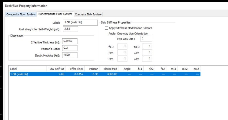
ASCE says un-topped metal deck is flexible if lateral system is braced frames (the alternative being, with moment frames, we can't consider it to be flexible).

As I have combined lateral systems in the same direction and an un-topped deck, is it safe to consider the diaphragm to behave as flexible ? If I consider it to be semi-rigid all of the load is dragged into the braced frames. My intuition is that due to the combined systems, the diaphragm will behavior somewhere between a flexible and a semi rigid. I talked to a few engineers and they mentioned that its safe to consider it to be a flexible diaphragm
 
Replies continue below

Recommended for you

Samwise said:
I do not want to make the braced frames more stiff as they will attract more load into the tower roof. I have moment frames elsewhere.
This one was a typo on my part. I`ve editing the original post to fix it. I meant to say that stiffening the *moment frames* will attract more load to them, and reduce load to the braced frames.

Samwise said:
What is the stipulation for diaphragm to behave as flexible with respect to wind loads. I don't think we can use the ASCE 12.3.1.3 right ?
I think this is an awesome question. ASCE seems to be oddly silent with regard to diaphragms for wind loads. I default to the seismic requirements because no additional guidance seems to be provided.
 
That is the same approach I would take, would you mind sharing a screen shot of the deck properties in RAM.

As far as the flexible/rigid provisions being defined in the seismic chapter and not wind I would say it doesn't matter the rigidity of the diaphragm is a physical property and independent of the loading. Regardless though you are doing a semi-rigid analysis which meshes the diaphragm and provides the most realistic approximation of the response, provided the inputs are acceptable.
 
Celt83 said:
Sure thing, see the snip below


RA_properties_ny4bku.jpg
 
The physics/engineers guides the code not the other way around.

It doesn't matter what the code says. If you have a rigid structure rigidly connected to a flexible structure then you are going to attract significantly increased loads.

I know others have said similar but I wanted to emphasise that the code here is largely not relevant. Look at the ACTUAL behaviour.
 
The flexibility of a moment frame versus a braced is going to create really odd force distribution (I mean disproportionate) regardless of the diaphragm flexibility, further, the working on "considered flexible" doesn't mention moment frames for a reason. The described vertical elements are shear walls and braced frames, both fairly rigid which will tend to produce flexible diaphragm behaviour and force distributions. It is unlikely you'll be able to establish it as calculated as flexible (12.3.1.3) because of that, as well.

This is the sort of thing that is an analytical mess. Unless you design the moment frames to be so stiff that they are comparable in deflection to the braced frames (which will involve a lot of material for the structural caprice of a simple roof diaphragm analysis and force distribution).

ETA - the code is ALWAYS relevant. Even when it is silent on a subject..... to justify flexible diaphragm force distribution of ANY lateral load you're obligated to do it based on established principles of mechanics. That's where your wind load provisions for the analysis lie, not explicitly in ASCE 7 Chapter 12 (which is seismic), but Chapter 12 of ASCE 7 is based on established principles of mechanics and generally accepted by the engineering community, peer-reviewed, etc.

IBC_1604.4_Analysis_yaykmr.jpg
 
thanks, that is about what I would expect. Some things to try:

- Disconnect both braced frames from the diaphragm entirely, check that you get reasonable deflections with the moment frames (around 0.9").
If not upsize the moment frames​
- Disconnect the braced frame that is not attached to the diaphragm.
- Reduce maximum mesh size down to 2 ft in RAM Frame.
- If you happened to disconnect any nodes on the moment frames from the diaphragm make sure they are reconnected for the semi-rigid analysis.
- Add a load case to compute the center of rigidity, and verify the result makes sense.
 
I did some simplified model tests with roughly your proportions and found that if the braced frame is around 5-8x the stiffness of the moment frames it will absorb most of the shear and the diaphragm will behave close to rigid.
 
Celt83 said:
That is what I was getting too. The braced frame drags about 70-80% of all the load. Also, there is no diaphragm that extends into the tower roof. Its only the beams from main building that connect to the tower roof which take all the load.
 
Pics of the simplified models I ran, note this didn't include shear deformations but it gives a rough approximation showing when a single braced frame starts dominating. Ran it with K,braced frame = 100xK,moment frames down to Kbf = Kmf.

100x
k_100x_c9erad.png


10x
k_10x_supclp.png


5x
k_5x_jffk3u.png


2x
k_2x_egwsdh.png


1x
k_equal_qtykpd.png
 
Lexpatrie:
Simply 2d frame program I am working on.

The model uses a beam with the flexural properties from sam’s earlier post, 200ish plf edge load, 4 k/in springs at the moment frames and then I varied the spring stiffness at the singular braced frame. I put the frame directly in line with the central moment frame and connected them together with a hinged but very axially stiff truss bar to mimic a rigid link. Any commercial node/bar based software can likely get similar/better results with the notable difference of including the shear deformation component.
 
Status
Not open for further replies.
Back
Top