EngStuff
Structural
- Jul 1, 2019
- 81
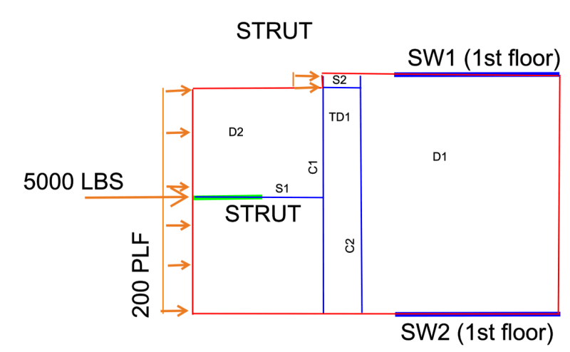
My question is regarding point load transfer with a distributed load and a notch. I also drew an image. see below
A quick description
Working on a custom home. Stuck with this layout so cannot add or remove shear walls/beams columns.
1. Blue walls are first floor shear walls.
2. Green wall is 2nd floor shear wall (non load bearing).
3. 200 plf wind load with a 5k center load from the 2nd floor shear wall.
4. 2nd floor shear wall is supported by a beam/column(not a moment frame).
Beam/column will not resist shear and will not be a moment frame due to the fact if it is, i would have to take a strut all the way to the right side. So it will only see uplift and downward force.
Note: I am following part of terry malones example.
My thoughts + question
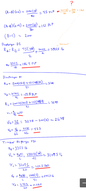
1. Can we stop the strut for the 2nd floor shear wall @ collector "c1" on d2. Also, if we were to do that, do all the 5k load go into the diaphragm d2 and none on diaphragm d1. If we can, I don't see how I can get 200 plf distributed between d1 and d2 and 5000 only on d1.
Part of me thinks that 5k load will be distributed throughout d1 and d2. but my other thought is how can it unless i place a strut down the center the full length which I am not going to do that?
2. Do I take the strut s1 into the transfer diaphragm and all the 5k load transfers within the TD1?
Pretty much stuck on how to do this. I think I got the layout done correctly, but don't have the right idea on how to transfer the 5k force.
Thanks
A quick description
Working on a custom home. Stuck with this layout so cannot add or remove shear walls/beams columns.
1. Blue walls are first floor shear walls.
2. Green wall is 2nd floor shear wall (non load bearing).
3. 200 plf wind load with a 5k center load from the 2nd floor shear wall.
4. 2nd floor shear wall is supported by a beam/column(not a moment frame).
Beam/column will not resist shear and will not be a moment frame due to the fact if it is, i would have to take a strut all the way to the right side. So it will only see uplift and downward force.
Note: I am following part of terry malones example.
My thoughts + question
1. Can we stop the strut for the 2nd floor shear wall @ collector "c1" on d2. Also, if we were to do that, do all the 5k load go into the diaphragm d2 and none on diaphragm d1. If we can, I don't see how I can get 200 plf distributed between d1 and d2 and 5000 only on d1.
Part of me thinks that 5k load will be distributed throughout d1 and d2. but my other thought is how can it unless i place a strut down the center the full length which I am not going to do that?
2. Do I take the strut s1 into the transfer diaphragm and all the 5k load transfers within the TD1?
Pretty much stuck on how to do this. I think I got the layout done correctly, but don't have the right idea on how to transfer the 5k force.
Thanks