Continue to Site

Eng-Tips is the largest engineering community on the Internet

Intelligent Work Forums for Engineering Professionals

  • Congratulations KootK on being selected by the Eng-Tips community for having the most helpful posts in the forums last week. Way to Go!

Die Cast Overmolding

Status
Not open for further replies.

LL631

Industrial
Nov 30, 2018
24
Is die cast overmolding possible? specifically, die casting aluminium to overmold a steel part?

A quick scan of google suggests not, possibly due to the high shrinkage rate of aluminium?

We have a die cast aluminium rotor that we would like to incorporate a steel rim into to act as a target for a hall effect speed sensor (making the entire rotor from steel is not a good option).
 
Replies continue below

Recommended for you

I've heard of it being done, e.g. stainless steel or copper tubing through an aluminum/zinc heat sink; in that case the higher shrink of the aluminum just puts compressive stress on the tubes. In your application, the aluminum will try to shrink radially inwards, away from the steel rim.

If you cast or machine a groove in the aluminum rim, then bolt or weld a steel ring into the groove, would that not work? Not welding steel to aluminum, but making a radial weld on a gap in the steel rim, so that it "shrinks" to fit snugly to the aluminum.
 
Sorry trueblood I missed your reply.

The idea of overmold casting was to eliminate additional production steps to keep costs down, but I think your right that the shrinkage is not going to work in this application.

I hadn't thought of welding the rim I'll take a look at that.

Cheers
 
Could you just mold in some small steel pieces to trigger the sensor?
Do you need a full rim?
You could mold in steel "T" or "L" pieces, or straight ones with holes in them.

= = = = = = = = = = = = = = = = = = = =
P.E. Metallurgy, Plymouth Tube
 
It doesn't have to be a rim but it will be 48/64 tooth so individual pieces will be impracticable and give bad tolerances. I had considered a rim with internal teeth which would be overmolded, the outer rim would then be machined away leaving the teeth inside, but I still have to figure out how to deal with the aluminium shrinkage.

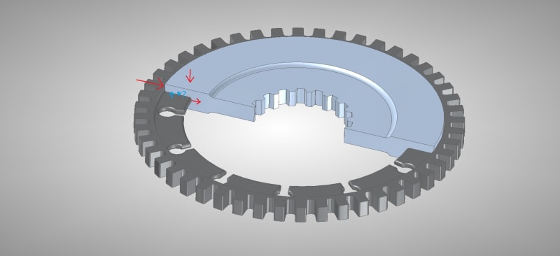
How would the aluminium shrink in a design like this? Would it shrink away from the web or onto it? For reference this model is 48T, OD = 77mm, Thickness = 6mm max
Cast_Assembly_ttkrse.jpg
 
It all depends on how/whether the alum. solidifies in the keyslots before the rest of it solidifies, and if radial stresses high enough to create voiding/tears develop as it solidifies and shrinks.
 
Thanks for the replies, I'll contact some suppliers to see what they think.
 
If cost and reliability are issues then a solid steel disc will likely be a better option.

= = = = = = = = = = = = = = = = = = = =
P.E. Metallurgy, Plymouth Tube
 
Unfortunately an all steel rotor is not an option as it's used within an EM brake where it tends to be pulled to the magnet causing heat and wear issues - the relatively small amount of steel in the rim and it's shielded location make it less of a problem. There is also the bother of re-certifying the spline interface on lengthy tests.

Going off topic so if you think this warrants it's own thread in the magnetic forum let me know. For the rim we are considering 3D metal printing but none of the suppliers can provide magnetic properties for their materials. As it is just the prototype I am not concerned with the exact properties but would at least like to confirm it will have reasonable permeability, what do you think would be the best bet between maraging steel (1.2709), H13, A2, D2 tool steel(ASTM)?

Capture_jtqms2.png
 
How fast are you spinning this?
Why are you looking at very high strength steels?
Tools steels make good permanent magnets, they are not magnetically soft materials.
Why not a plain low C steel?

= = = = = = = = = = = = = = = = = = = =
P.E. Metallurgy, Plymouth Tube
 
7,000 - 10,000 rpm. The only reason for choosing high strength steels is they are the only options I can get from 3D printing suppliers, I guess there isn't much of a market for spending £000's to manufacture cheap low strength steel.

We plan to sinter the production version in a low carbon steel which we know has the magnetic properties we are after. But before we launch tooling we need to prove the concept, hence the 3D printed prototype.

The prototype has two main goals: to prove the sensor design works & to trial the overmolding concept. The sensor is a back-biased differential type so is detecting the change in magnetic field caused by the influence of the toothed gear, so although not ideal I think a magnetically hard material should still work, maybe?


Speed sensors will work, if properly calibrated, on any ferromagnetic material...or so I've been told.

I wonder if a plated (or flame spray deposited?) coating of iron/steel might be enough to trigger the sensors? I've used thin (.032 inch thick) 430 ss shim stock for a hall effect sensor target, though not at that speed.

Would optical/IR sensors work in your application?

Past all that, you could machine the gear segments with dovetails that fit into a similar dovetail cuts on the aluminum disk (like the fir trees used to hold turbine blades on disks in turbojet/turbofan aircraft engines).
 
Status
Not open for further replies.

Part and Inventory Search

Sponsor