Jekei
Civil/Environmental
- May 17, 2020
- 6
Hi,
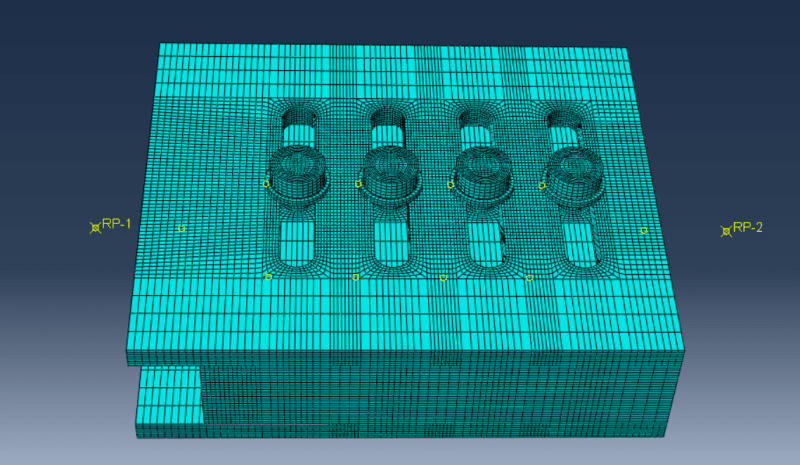
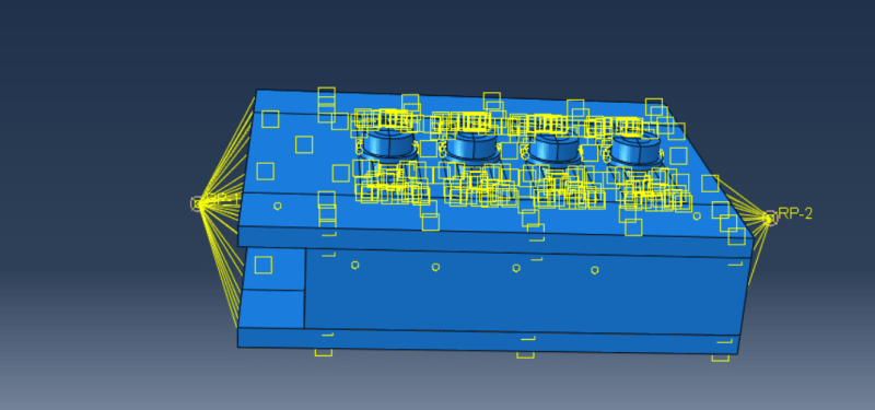
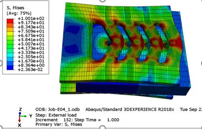
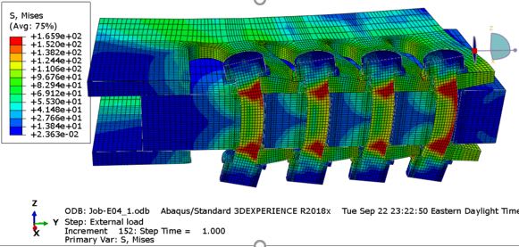
I am modelling a bolted connection in double shear. Force is applied, on central plate, as a displacement using a BC at a reference point. And history output is also requested at this reference point for both the displacement and force(for the plot).When I compare my analytical result(force Vs displacement) from Abaqus with experimental result ,the plot from my analytical result is quite below the experimental plot. My material property data is correct and also I tried many time changing the meshing of the model just as to get the desired result but still the result is below the experimental value. I would appreciate if some one could suggest what might be the reason behind the difference between these plots.
( I am specially concerned about the differences I get towards the yielding point and after that)
The plot attached:


