Continue to Site

Eng-Tips is the largest engineering community on the Internet

Intelligent Work Forums for Engineering Professionals

  • Congratulations KootK on being selected by the Eng-Tips community for having the most helpful posts in the forums last week. Way to Go!

Different mesh density on the individual part 1

Status
Not open for further replies.

polak7

Materials
Jan 23, 2015
52
Hello,

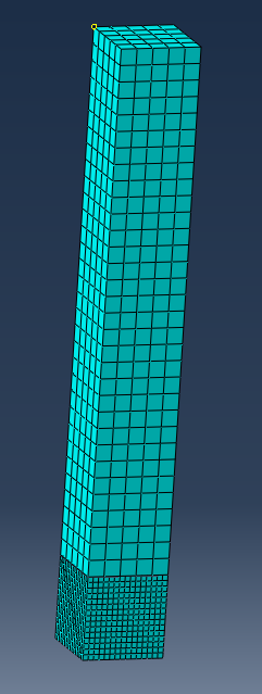
Look at the figure:
Capture_stw4j2.png


Here are two parts TIE'ed together and the mesh densities on them are different. Is it possible to obtain the same results using one part with partitions? I tried to do that, but I can only change the number of elements on the thickness of partitions.
 
Replies continue below

Recommended for you

It is possible to get this mesh with one part and a partition, but it still would have a Tie in it. The Tie would be added automatically. Otherwise you would have nodes at the fine mesh that are not attached to the coarse mesh. That wouldn't make sense.
 
I see. How can I do it with the partition? It is good that Tie will be added automatically, because it will save a lot of time. And saving time is the purpose why I started this topic.
 
The Tie will be added automatically (a message is shows to the user), when the mesh settings are incompatible at the interface. In your case the element type and meshing technique is probably compatible. But when you enforce at the edges of one region that you want to have large elements and you enforce at another region that you want to have small elements, then it would be incompatible were they meet. So you have to apply local mesh seed and specify, that the mesher cannot alter these settings. You'll find the option in the dialog of the local mesh seed.
 
What is the application and what kind of analysis are you planning on running? I am asking because the tied interface should be 'far' away from sensitive areas, if there is a choice. If you are running a static analysis, then it may not matter as much.

*********************************************************
Are you new to this forum? If so, please read these FAQs:

 
Mustaine,
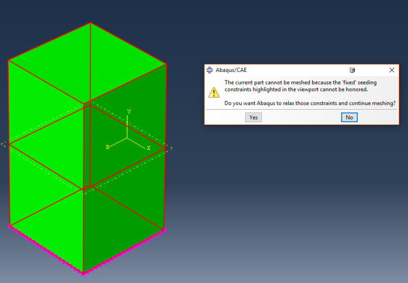
I did what you said. I enforced local mesh seed to two cells. Aprproximate element size was 5 and 1 respectively. I marked option: "Do not allow the number of elements to change". After that, when I tried to mesh the part, the message showed up:

Capture_d9vwjc.png


Did I something wrong?

IceBreakerSours,
It was rather general question. For now I do not plan the analysis. Usually, I perform static simulations.
 
Yeah, looks like I was wrong and A/CAE only adds Ties automatically when the element type is different or when the meshing techniques cannot create matching nodes at the interface.
 
Status
Not open for further replies.

Part and Inventory Search

Sponsor