Continue to Site

Eng-Tips is the largest engineering community on the Internet

Intelligent Work Forums for Engineering Professionals

  • Congratulations GregLocock on being selected by the Eng-Tips community for having the most helpful posts in the forums last week. Way to Go!

different results (bending moments/shear) for different cross sections (FEM)

Status
Not open for further replies.

gmd255

Structural
Apr 17, 2017
49
Im using software Tower 6 for FEM.
I have modeled 3 frames (same geometry but different cross sections/material for each frame):
MODEL 1: concrete 300/300 mm
MODEL 2: concrete 200/200 mm
MODEL 3: steel H section
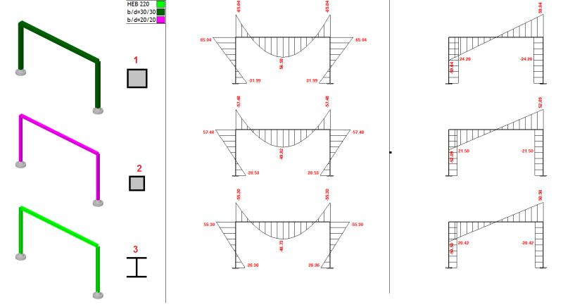
rsk_wcj1me.png


Im wondering why do I get so different results for each model? Looks like software takes into account the stiffnes of columns/beam (based on geometry and material)when calculating internal forces in elements?
I dont like it since you can design elements based on lets say model 1, but when you choose to change a section in the middle of design - lets say from 300/300 cm to 300/350 mm and you have different internal forces (moments, shear)...

How do you guys model stuff like this?

As far as I know, internal forces should be the same for each model (if we dont consider self weight of elements) - forces should depend on geometry of model and loads only...
 
Replies continue below

Recommended for you

When you change cross section you get different results.
You must re run the program with the new section and check if the section is sufficient for taking all the forces
 
Is the difference due to self-weight of the various cross-sections?

Are the column bases fixed against rotation, or is the stiffness less than infinite?

 
When you change cross section you get different results.
You must re run the program with the new section and check if the section is sufficient for taking all the forces

Yes, but I get different results even when self weight is taken as zero for all models.

Are the column bases fixed against rotation, or is the stiffness less than infinite?
columns are fixed - stiffnes is infinite.
 
With different depths of sections, you get slightly different clear spans, therefore different moments and shears.
 
Think about it. If you assume a basic model where I = x for both the column and roof beam, run the frame, and get the force distribution. Now run the same model but substitute 10x for x for the column only, run the frame, and you will see a substantially different distribution under the same loadings. Run the model a 3rd time but substitute 10x for x for the roof beam only and set the column back to x, run the frame, and you will see a 3rd distribution. The frame in question is not determinate so varying the cross-sectional properties will affect the results, particularly given your fixed column bases. If you run with pinned base columns, and run all of the frames with equal cross-section between the columns and beams, ignoring self-weight you should see pretty uniform numbers regardless of your cross-section.
 
The loads are different, as shown by the different shear force and total bending moment on the horizontal member. (Edit: or the loads are the same but the results are unreliable.)

I'm not familiar with the software. Is it the type that needs to be broken into a sufficient number of elements to get accurate results (and that hasn't been done)? Or is it the type where beam elements don't need to be sub-divided to get accurate results?

Can you check the sum of reactions? Do they match the applied loads (ie is it in equilibrium)?


the frame is indeterminant therefore changes in stiffness will change the internal reactions.

You're showing us shear (on the RH graph). These shears (equal and opposite) are driven by the model stiffness.

another day in paradise, or is paradise one day closer ?
 
the frame is indeterminant therefore changes in stiffness will change the internal reactions.

Changes in *relative* stiffness should change the results. GMD255 has not done that.

I've back-calculated the span of the horizontal member from the shear forces and bending moments:
300*300: 6.886 units (metres?)
200*200: 8.201 units
HEB220: 8.24 units (exactly)

However GMD255 says the geometry is the same. 200*200 and HEB220 are similar (though not exactly the same) but the 300*300 results are significantly different.

Also the 300*300 hogging moment is smaller than the sagging moment which is the opposite of the other two analyses. Without knowing the software and seeing the inputs, I lean to some sort of analysis error (convergence, discretisation?).
 
the ratio of EI/l of beam to column and the columns bottom restraint condition effect bending moment distribution
 
I've reproduced the HEB220 results as closely as I can in the attachment for two frames.

The frame on the left is made from 610UB125 steel I-beams (610mm deep, 125 kg/m weight). The frame on the right is 150UB14 (150mm deep, 14 kg/m). This is the biggest Australian rolled I-beam versus the smallest: stiffness varies by a factor of 49.

This shows what GMD255 expected to see: deflections are of course affected by the change to cross-section, but shear forces and bending moments are virtually unaffected.

Analysis error or unexpected difference in inputs (input error) are the most likely culprits IMO.

EDIT: I think I misread the corner bending moment on the 300*300 output diagram in the original post. So, the results for that cross-section are not as far off the other two cross-sections as I thought - please read my other comments with this in mind.


 http://files.engineering.com/getfile.aspx?folder=b8f3b358-6fef-4591-ade7-d7a34e7fc5ee&file=Frame_analysis_-_stiffness_varied.pdf
The output diagrams are not clear, but it looks like the differences are consistent with the difference being due to the self weight of the beams with a span of 8.25 m and load factor of 1.35, assuming a concrete density of 25 kN/m3.

Quick checks you can do are the difference in shear force between beam ends should be equal to WL, and the difference in bending moment between beam ends and mid-span should be WL^2/8.

As others have pointed out, if the columns and beam have different stiffness, or if there is a spring restraint at the base rather than fixed condition, the bending moment diagrams will be very different.

Coming back to your original point, if you are doing a computer frame analysis, and you change the section for any or all members, then yes, you do need to do the analysis again, unless you have done a separate calculation and are certain that the differences in results are not significant.

You should also always review computer results to make sure the results are consistent with mechanics and your intended loading.

Doug Jenkins
Interactive Design Services
 
I cannot read the results you are getting, but are you doing a large-displacement analysis without realising it?
 
Are you inputting all the dimensions and material properties into the program? If you input only the moment of inertia, and vary that, but keep the centreline conditions the same, your output should be the same. Your results are different because you have given the program a lot of information, not the minimum amount for analysis, the minimum amount being only centreline dimensions, loading, and support conditions.

 
It's hard to read the output, but in diagram 1, it appears you have a moment of 65.04 at the top of column and 45.04 at the end of beam. These moments should be equal unless you are applying an external moment at the joint.

If the boundary conditions are identical and ratio of beam stiffness to column stiffness is constant for all three cases, you should have identical results.


BA
 
It is very likely your FEM program is considering the shear stiffness/deformations of the cross sections which will vary between the square concrete and W steel cross sections you have.
 
Is there some lateral load and are you doing p-delta analysis?
 
Status
Not open for further replies.

Part and Inventory Search

Sponsor