Eng-Tips is the largest engineering community on the Internet

Intelligent Work Forums for Engineering Professionals

  • Congratulations waross on being selected by the Eng-Tips community for having the most helpful posts in the forums last week. Way to Go!

Difficult Concrete Soffit Repair

Status
Not open for further replies.

KootK

Structural
Oct 16, 2001
17,990
CA
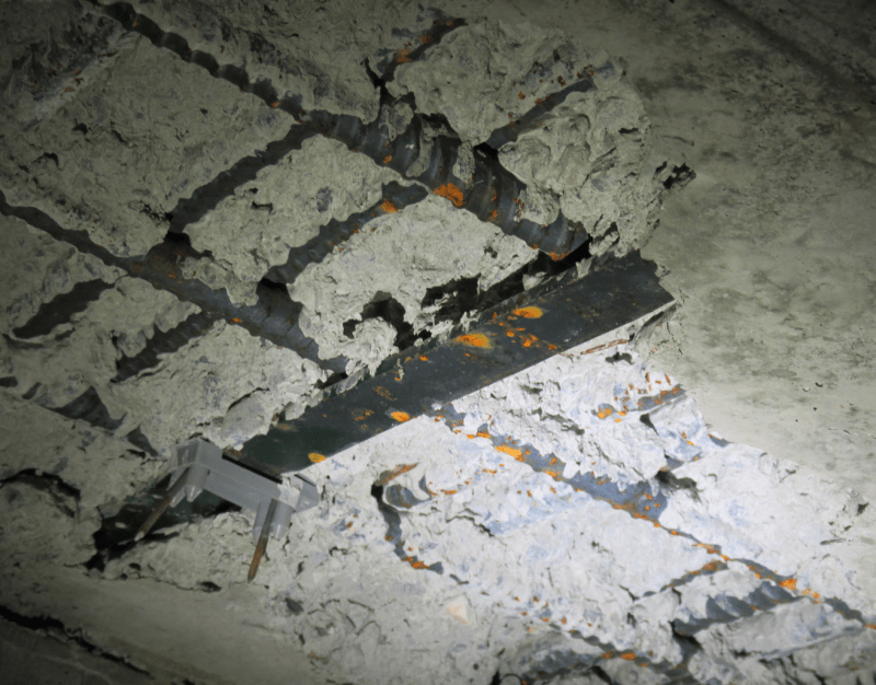
I'm seeking some advice regarding a difficult concrete repair that I'm undertaking. While I'm interested to discuss the possible causes of the problem, we're mostly just in problem solving mode at this time: how best to responsibly investigate and fix this. For context, everything that follows was copied from an email that I sent to our local Sika rep.

My cliff notes:

1) This is predominantly at column locations.
2) We suspect that uncleared snow on the form deck was likely the culprit here, perhaps in combination with vibration issues.
3) All of the stud rails are too low for cover in their current state. We’re contemplating additional concrete cast below the existing soffit level.
4) We have some concern for the snow having melted into the concrete and messed with the water content locally.
5) We have reason to believe that we have this same issue not just beside our columns but above them. This creates a soffit repair access problem.
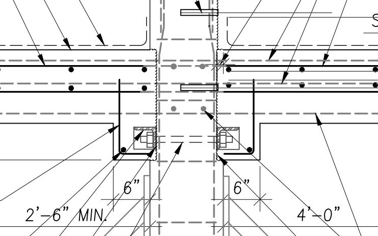
6) As you can see, these areas are quite congested with two layers of bottom steel, integrity steel in two directions, and stud rails. It’s a lot of stuff to climb over top of with a repair.
7) My instinct with this kind of thing is to chip concrete away at least 1” above the uppermost rebar before coming back with repair material. That, both for repair longevity and for getting a convincing bond between the bars, the repair material, and the existing substrate. As you mentioned, Hilti has confidence in it’s partial depth repair solutions. You’ll need to dust your salesman hat off and see if you can convince me of the same as I’ve no doubt that our contractor would prefer that.

Here’s a rough outline of what the engineer in me has been contemplating as a hard line repair strategy:

1) Sandblast the soffit to clean things and remove any material that might have been weakened by a higher than normal water content.
2) Hydrodemolish the slab through its entire thickness at areas where we will be doing significant repair. This is not how we make friends.
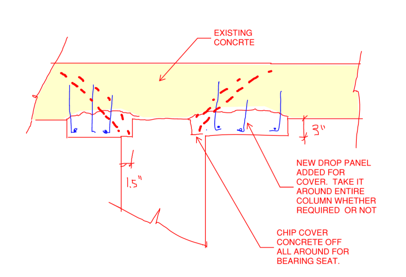
3) Form new, drop panel-ish looking things below the existing concrete soffit to get us right with cover requirements. Vertical dowels etc.
4) Install our repair material from the top. Low/no shrinkage stuff that flows well.
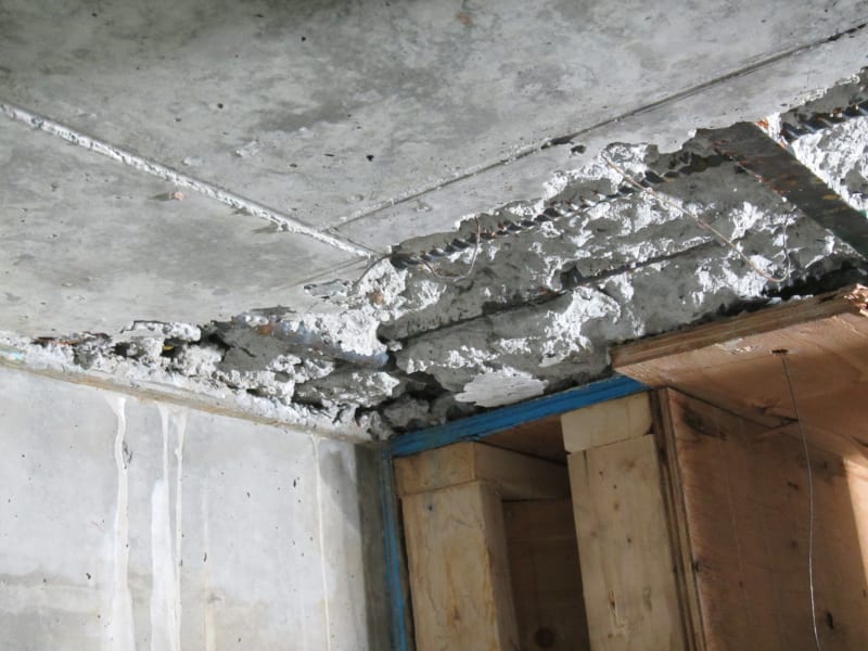
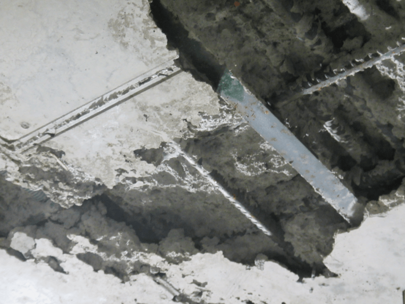
c01_fqeood.jpg

c02_sc1kaw.png

C01_klp8hl.png
 
Replies continue below

Recommended for you

KootK said:
The petrographic analysis sounds good. Can it be expected to provide data particular to various locations within the slab depth as opposed to just an average of the slab thickness as a whole?

Even with petrographic analysis it'll be hard to distinguish right at the boundary. IMHO your best bet is to core the problem area and take cores of adjacent, presumed good, areas and compare under a microscope in addition to the other standard tests. At least that way you can tell if it is relatively worse than the other areas.

KootK said:
How do we feel about the potential for their to be crappy concrete right over the columns? Can that be assessed in some way? When the chipping is done for the repair, will it be feasible to try to chip laterally into that space?

Agree with Ingenuity that the feel of an experienced worker on the end of a chipping hammer is the best way to assess. Sandblasting will just create a bunch of sand you need to pick up. Though I think he is a tad aggressive on his weight...you could get a feel for the really bad concrete with a 7lbs electric hilti. 15lbs for sure. 30lbs is too heavy IMHO for this kind of exploratory procedure but maybe I'm just a weak SOB lol

You can definitely chip somewhat into the space (unless bars are stacked side by side) but be careful as repairing that concrete (given its location) may be problematic. And really, if it's bad just above the column what's the problem other than that's not ideal? It's confined, bearing wont be an issue, shear likely not a problem. I think by chasing the repair over the column you'd run into more issues than you would solve especially since if you take out too much vertical loads become a real concern.

By the way, I've been thinking and if this was due to snow (and it absolutely might be) I find it extremely strange that the original EOR didn't force them to repair it at the time of construction. It would be...unusual for this kind of noticeable deficiency to escape correction at the time of construction. Unless the EOR saw it and had a heart attack on-site and no one said anything?
 
The primary reasons for chipping an inch beyond the reinforcing steel usually relates to A) having sufficient clearance around the rebar for the coarse aggregate in the repair mix and B)being able to clean the rebar properly around it's entire perimeter before patching. With respect to B, normally we are removing delaminated concrete that resulted from rebar corrosion, thus we want to clean up the rebar. However, it appears in your case that the rebar is not corroded. With a more 'standard' rebar layout, and clean rebar, I likely would ask for the inch behind the rebar anywhere more than 50% of the perimeter of the rebar had been exposed.

Thoughts on how to determine which areas of the concrete may be weaker. I doubt sandblasting will have any affect. An experienced labourer with a 15lb jackhammer can usually identify significantly weaker areas as they move along, although it really takes the right person. I once reasonably successfully identified the extent of a bad load of concrete in a suspended slab via Windsor Probe. We did not care about the actual MPa values, we were looking at relative strengths.

You would likely be able to find the weak areas with hydrodemo. I really like hydrodemo, however, if the site is remote I can see it not being a great option. I have been on quite a few projects where there were significant amounts of soffit repairs jackhammered with 15 lb'ers. If there is a larger quantity grouped together, we would tend to turn the soffit repairs into through slab repairs, but this was typically in parking garages where access above and below was not a problem.

I am going to think on this a bit more, interesting problem. Lots of options. Full slabs have been dropped and replaced, tied back in to the existing columns/walls. With the right shoring, the full concrete cross-section of columns have been removed and replaced.
 
Enable said:
And really, if it's bad just above the column what's the problem other than that's not ideal?

1) Compression, particularly where there is a column above.

2) Compression in the sense that all of your punching shear comes into the column through diagonal struts that, presumably, hit the middle of it.

3) Punching shear in the sense that, if the concrete is bad enough, you could develop vertical shear planes right beside the faces of the column.

4) Compression if, somehow, there's actually void over the column.

5) I don't love my integrity steel being embedded in crap over the column but that's not a deal breaker for me.

But, yeah, in general I agree that the concrete is likely working much less hard over the columns than beside them

Enable said:
I think by chasing the repair over the column you'd run into more issues than you would solve especially since if you take out too much vertical loads become a real concern.

Agreed, I approach most of these things from a first, do no harm perspective. There would be shoring in place while this is done.

Enable said:
Unless the EOR saw it and had a heart attack on-site and no one said anything?

I believe that the EOR saw the snow, noted that it needed to be removed, but did not return to verify that it had to be removed. Like I said at the top, we're mostly in friendly problems solving mode. At least, for now we are.


Aw I'm silly this is a new build. Should have caught that. Hence why it's open for now and the steel isn't rusted to all hell. Sorry about that.

Most of your comments re: concrete above are what I'd lump into unideal (okay fine maybe I over sold that...very less than ideal. But sometimes you just got to let your hair down). Though one thing you mention that is definitely worth pondering is the possibility of voids. I wouldn't expect there to be large voids since the boundary of the issue seems to be pretty well defined. On the other hand, that's a risk and a significant one and you shouldn't have to take that on coming into this situation from afar. You're probably right to think about that and get it scanned or possibly x-rayed for the level of detail you'd need.

BTW if you are concerned about the shear at the face of the column you can always do the typical haunch + angle detail we use for through-slab at existing columns. Kind of like below. Though if this is new construction you'd probably try to MacGyver a detail so your integrity bars are in-situ welded to a plate that gets welded to the angle or something to help satiate the EOR (if you can anyways...haven't really thought through how'd you do that so fair warning).

Typical_Repair_c2mwne.jpg
 
kootk said:
The petrographic analysis sounds good. Can it be expected to provide data particular to various locations within the slab depth as opposed to just an average of the slab thickness as a whole?

There are certain properties I know are looked at through the depth, like carbonation and chloride analysis. I would expect that w/c ratio and air voids could be evaluated through the depth of a core as well but I'm not positive. I will send you example results.
 
From ACI 437:
A petrographic analysis is normally performed to deter-mine the composition of concrete, assess the adequacy of the mixture proportions, and determine the cause(s) of deterioration. A petrographic analysis performed in accordance with ASTM C856 can provide some of the following information about the concrete:
a) Density of the cement paste and color of the cement
b) Type of cement used
c) Proportion of unhydrated cement
d) Presence of pozzolans or slag cement
e) Volumetric proportions of aggregates, cement paste, and air voids
f) Homogeneity of the concrete
g) Presence and type of fibers (fiber-reinforced concrete)
h) Presence of foreign materials, including debris or organic materials
i) Aggregate shape, size distribution, and composition
j) Nature of interface between aggregates and cement paste
k) Extent to which aggregate particles are coated and the nature of the coating substance
l) Potential for deleterious reactions between the aggregate and cement alkalis
m) Presence of unsound aggregates (fractured or porous)
n) Air content and various dimensional characteristics of the air-void system, including entrained and entrapped air
o) Characteristics and distribution of voids
p) Occurrence of settlement and bleeding in fresh concrete
q) Degree of consolidation
r) Presence of surface treatments

Petrography can also provide information on the following items to aid in the determination of causes of concrete deterioration:
a) Occurrence and distribution of fractures
b) Presence of contaminating substances
c) Surface-finish-related problems
d) Curing-related problems
e) Presence of deterioration caused by exposure to freezing and thawing
f) Presence of reaction products in cracks or around aggre-gates, indicating deleterious alkali-aggregate reactions
g) Presence of ettringite within cement paste (other than in pore system or voids) and in cracks indicating sulfate attack
h) Presence of corrosion products
i) Presence of deterioration due to abrasion or ire exposure
j) Weathering patterns from surface-to-bottom

I'm making a thing: (It's no Kootware and it will probably break but it's alive!)
 
I'd been considering installing something drop panel-ish for the sake of restoring cover where it's been compromises. Now, I'm starting to wonder if I should deliberately create something that would be more like a real drop panel with respect to it's potential to improve shear and bearing capacity at the column.

How do we feel about this?

C01_ldrdxn.png
 
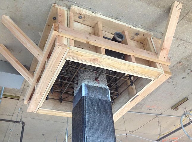
Yep, entirely appropriate, and been done many times before.

Form-and-pump from below.

SCC_FORMS_wdvalp.jpg
 
Agree with Ingenuity. That is a viable alternative and like he said not uncommon in the least.

Just a few notes re: bearing seat

A) Chipped profiles are rather irregular and so if you want a 1.5" shelf you should specify it as a a 1.5" minimum. The amplitude of a chipped surface is usually at least the size of the aggregate, so with a typical 3/4" mix you're looking at removing 1.5-2.5" per side of the existing column. If you don't demand a 1.5" minimum you are likely to wind up with 1.5" at the base but much less in the middle (sometimes darn near 0). EDIT - You'll want to be careful about location of the vertical bars as well, they are not necessarily where they are supposed to be and sometimes might be as close to the surface as 3/4" (or less). So if you instruct to go 1.5" you'll need to make a note that they are not to go around vertical bars should they be encountered closer to the surface than anticipated. This being a new build that might be less likely though.

B) Depending on how large your column is that 1.5 - 2.5" can actually add up to quite a bit as it's all sides (EDIT - also factor in workers propensity to chip more than that in areas). You start to get concerned about vertical loads on existing structures (EDIT2 - especially since deterioration extent is unknown and you may take out more than cover by accident), which is why we typically use the angles or rely on dowels with a 1" or less key instead. However, in your case you can probably take the load off fairly easily since the structure has yet to be built. Timelines will be critical for you on that one I'd suspect (don't want them to throw too much load up there to the point simple post shores around cant deal with it anymore)

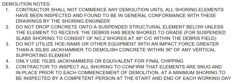
C) I would restrict hammer size to 15lbs max around the column to avoid microfractures between the column and the vertical bar. Below are some notes I sometimes use when I need to restrict hammer sizes. Large fractures are also a concern since when they hit the bar with the hammer the bar obviously vibrates and can cause damage, especially with the larger sized hammers

Capture_tiemra.jpg
 
I agree with Enable's comments about percussion chipping hammers and bruising/micro-fracturing. Best to use the smallest possible tool to do the required job.

My main 'issue' with 15lb or less percussion hammers is that they are typically 'SDS Plus' connector for bits and they are hard to get in bit length of >10". Whereas with > 15lb'ers they are typically 'SDS Max' connectors and your choice for bit length goes from 10" up to about 30". Bit length is sometimes critical when you have to get behind dense rebar at odd angles, with significant/unknown chipping depth.
 
Very good advice. On my current project we've had a number of similar repairs, albeit less severe, and have had good results with EucoRepair V100. I'm not affiliated with Euclid or anything, we tried a number of different repair materials (namely SikaRepair 224 & 223, and an Ardex product) which worked, but were a little more difficult to work with. The quality of the mason installing the mortar really makes a difference. We had some difficulties with bonding, but I can't say whether that's the product or the workmanship. We've found the V100 is a little more dummy-proof (but likely has other drawbacks). Just my 2 cents.
 
Status
Not open for further replies.

Part and Inventory Search

Sponsor

Back
Top