Continue to Site

Eng-Tips is the largest engineering community on the Internet

Intelligent Work Forums for Engineering Professionals

  • Congratulations cowski on being selected by the Eng-Tips community for having the most helpful posts in the forums last week. Way to Go!

Difficulty applying datum simulation of two coaxial features - cone and cylinder

Status
Not open for further replies.

JNieman

Aerospace
Mar 26, 2014
1,128
Referencing ASME Y14.5-2009
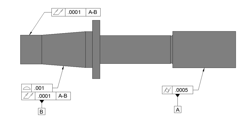
I'm looking at section 4.12.2 and referencing Figures 4-25 and 4-26.

I have a question regarding the best/proper practice in holding or simulating datums on a part, to inspect total runout. The situation I'm faced with is a single datum axis simulated by two coaxial features, one being cylindrical, the other conical. Below is a rudimentary sketch simulating my part.

If we are to create a tapered ring to match the nominal condition of the conical feature -B- and a ring to simulate the cylindrical -A-, I'm not so sure how this really, functionally, plays out. I am having trouble wrapping my head around how successful this inspection method would be. Is there a fundamental flaw in my imagined setup, or in the nature of the features establishing a datum?

To ease setup, should I instead have a ring for both features, letting the taper simply settle at a single location? That would use -a- center -point- of the centerline of datum B, though. I'm a little confused.

Does anyone have some insight into how to approach this situation? Assuming I'm correct in how I am applying a datum established by two coaxial features (correct me if I'm wrong) this is more of an inspection method / gaging question, but I don't know a better place to ask.

Thank you in advance.
RUNOUT_pyi26t.png
 
Replies continue below

Recommended for you

JNieman

I am trying to think through an inspection fixture. I think your taper works if you add a vertical datum feature, either that flange, or the right-hand end.

--
JHG
 
Unfortunately the part in question is a part we're making for someone else. We're in communication with them as to function of those features, and how they would validate incoming parts, to ensure success. I also found it to just be an interesting challenge.

I don't know for sure but it seems like a tapered-bore bearing that must be inline with a stack of bearings on the straight shaft.
 
JNieman,

I am looking at that thing again. A profile tolerance on the taper must account for position along the axis. You need them to revise their drawing. Runout works. An angle tolerance works (I think). Profile does not work.

--
JHG
 
I have no idea what they are thinking and I believe that they don't either.

Don't most machine tool holders use the taper as the primary locating and orientation feature alone and depend on elastic deformation to allow the drawbar to pull them until the shaft flange makes axial locating contact?

I guess you can use a(n expensive) split collet that will conform to both the diameter and the taper variations, but at RFS one can use a mallet to get anything to fit if it gets hit hard enough.

This arrangement of [A-B] doesn't really say that [A] is particularly well aligned to just because the converse is true.
 
I agree with your sentiment. We have a pretty good and long relationship with this customer, so the likely conclusion will be another case of "Yea, we wrote that... but here's what we really want <long explanation or pictures of physical inspection setup> " and we take notes on the part in our ERP and inspection paperwork. I appreciate the effort in trying to "make this work" some how. The thought exercise helped stretch my brain cells a bit, so to speak.

No it's not ideal. No it's not by the book. But it gets good parts made, deadlines met, and us paid.
Occasionally we'll see revised prints from them.

Side note: In the context of tool holders such as in common milling machines, most styles don't even have contact with the flange. Only recently (afaik) has dual-contact holders came into commonality which allow for the flange to contact in addition to the taper. Otherwise, it's all taper and friction.
 
Every figure in 2009 concerning runout uses circular runout for non-cylindrical surfaces. This is true for my GD&T textbooks also. I had assumed that this was simply due to ease of measurement. Since you need to position the indicator normal to the surface being measured, circular runout is a much easier measurement to take than total runout for convex and concave surfaces. Do people use total runout on conical surfaces typically? We do not use runout very frequently at my work and when we do it is circular runout so I am just curious.
 
I assume that if one were to use total runout, you would have to have a setup which allows the indicator base to move along the nominal form of the shape being measured. So for a conical surface, the indicator base would have to translate along the basic angle somehow. I can see this being quite doable if it were worth the investment. It'd be like having a pantograph machine much more accurately, or one of the old duplicator machines that runs off of a 'master' part, in theory.

I don't know of any modern examples of doing such a thing, personally, so I don't know if it's a common practice. When inspection was required to be very precise on tapers, I've seen a form of layout fluid on a master which is then mated with the opposite taper being inspected (male to female), with a requirement for some percentage of fluid transfer on the overall surface. "Bluing" a surface to another, using a master.

While I've done such things for a simple "matched sets" of items or "one offs", to speak of using that method for production quantities would be a bit outside my experience.
 
JNeiman,

I think the truth is that good parts get made by disregarding the available tolerance. I would like sometime to see a supplier send parts back that are obviously useless but meet the print to emphasize that the guys doing the D&T work aren't adding any value and should either quit or learn to do it right. But I'm sure purchasing would blame the supplier, so that won't happen. Cn u igmine f lgl kapt meeking spling errs on carrects?
 
Status
Not open for further replies.

Part and Inventory Search

Sponsor