Continue to Site

Eng-Tips is the largest engineering community on the Internet

Intelligent Work Forums for Engineering Professionals

  • Congratulations cowski on being selected by the Eng-Tips community for having the most helpful posts in the forums last week. Way to Go!

Dimension and tolerances on an ISO view (2D drawing)

Status
Not open for further replies.

greenimi

Mechanical
Nov 30, 2011
2,391
(I asked this question in a different thread - with no answer- and I am going to ask it on a separate discussion too)

Do you think it is ALLOWED (per rules, regulations and stipulations) by the ASME standard to dimension a feature in an ISO view?

Scenario:
A 2D drawing is chosen as a method to communicate the design intent. Should/ shall all the feature's definition be shown in the applicable 2D views (front, left, right, section views, details)?
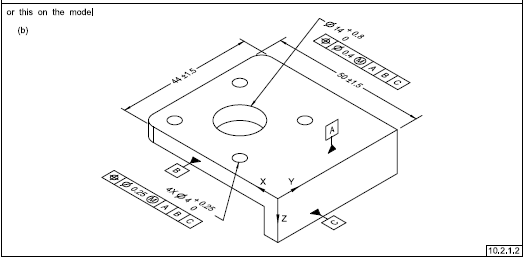
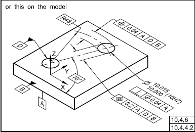
(NOT into the 3D ISO view). Or, maybe, you can have some of the dimensions, tolerances, notes, etc. shown in the ISO view?


My opinion (and I might be very well wrong and I cannot find a definitive answer in the ASME standard)
ISO view it is there / it is shown for easy to understand the part/drawing, but no dimesnions, tolerances should be part of the definition on the ISO view.

 
Replies continue below

Recommended for you

And the single mention of axonometric view in the standard is: "The “all around” symbol shall not be applied in an axonometric view on a two-dimensional drawing." Para. 11.3.1.3
 
Thank you for your replies.
We all know that the figures in the standard are intended only as illustrations to aid the user in understanding the practices described in the text.

From the same standard Y14.5-2018: Some figures are illustrations of models in a three dimensional environment. The absence of dimensioning and tolerancing annotations in a view may indicate that the product definition is defined in three dimensions.

Again, I am looking for for paragraphs within ANY Y14 set of standards where this practice (of having dimensions, tolerances, notes in the ISO view) is legalized.
 
Y14.5 gives two examples in most of its cases indicating the environment. "This on the orthographic view..." or "This on the model." One indicates a 2D view, the other a 3D annotation.
I've yet to see an axonometric view other than 7-49 & 7-50.

In my words this means that either 2D or 3D is appropriate for dimensioning. Nothing in between.
 
greenimi said:
Again, I am looking for for paragraphs within ANY Y14 set of standards where this practice (of having dimensions, tolerances, notes in the ISO view) is legalized.

Instead, try to find where it is illegalized. If you can't, it is legal.

Also, my logic is that since the committee found it necessary to outline that, as quoted above by Wuzhee, "The “all around” symbol shall not be applied in an axonometric view on a two-dimensional drawing”, then a profile tolerance CAN be shown on an axonometric view without the all-around symbol.

The advantage is that when complex geometries are involved, dimensioning and tolerancing in an axonometric view is useful for avoiding cluttered multiple sheet drawings with numerous auxiliary projections to show the true view of every feature.
 
Could somebody please explain me why Fig. 7-49 doesn't qualify as proper ISO view where "you can have some of the dimensions, tolerances, notes, etc. shown..." (greenimi)


"For every expert there is an equal and opposite expert"
Arthur C. Clarke Profiles of the future

 
Burunduk said:
when complex geometries are involved, dimensioning and tolerancing in an axonometric view is useful [...]
Just like my case in [link thread1103-506935]Link[/url]
 
greenimi and All,

There are figures in Y14.5 with dimensions in a model-based isometric view. Figure 10-3 in Y14.5-2018 is a good example. The basic dimensions are not explicitly annotated, because they are defined by the model. The directly toleranced dimensions (the hole diameters, and overall length and width) are. There is also Figures 10-2, 10-17, 10-19, 10-26, 10-35, 11-6, 11-8, 11-31, 11-32 and others that have directly toleranced dimensions in the model-based view.
Fig_10-3_model_view_h207rg.png


There was a figure in Y14.5-2009 (Figure 7-3) that was very similar to Figure 10-3 in 2018. The "screen image of digital data file" had the hole diameters but not the overall length and width. The 10-3 version in 2018 has directly toleranced dimensions for the overall length and width.

So the general methodology appears to be that basic dimensions are not shown in the model-based view, but directly toleranced dimensions are. But just to muddy the waters a bit more, in Figure 10-30 there are basic dimensions (a basic radius and basic angle) shown in the model-based view as well as directly toleranced hole diameter.
Fig_10-30_model_view_pm7voq.png


Evan Janeshewski

Axymetrix Quality Engineering Inc.
 
Evan,
I understand the notation in the standard "or this on the model" to say that the shown part of the figure is a depiction of the model, not of a model-based view in a 2D drawing sheet.

Regardless, I don't think there is any restriction against specifying dimensions or tolerances of any kind in an axonometric view in the drawing (apart from the bit about all-around that was already mentioned here). I also don't think that such restriction would make sense.
 
greenimi,

Is there any reason we should not dimension isometric drawings?

There is a reason we cannot dimension them. 3D CAD packages like SolidWorks cannot make the fonts work in isometric space. It would be nifty if someone developed some isometric fonts, i.e., fonts slopped 30[°] forwards and backwards.

--
JHG
 
I have to agree with Burunduk - "find where it is illegalized. If you can't, it is legal"
I don't know if this helps or not, but using ISO views on your drawing to fully define your definition is allowed...
Per ASME Y14.3-2012 section 9:
"To facilitate presentation of a design model and its
annotation, views depicting different orientations of the
model may be defined and saved in the digital data set.
See Fig. 9-1. These saved views may be used on drawing
graphic sheets that are part of the digital data set.
Drawing graphic sheets containing saved views may
fully define the product definition, or be used in conjunction
with the model or design model to fully define
the product."

"Know the rules well, so you can break them effectively."
-Dalai Lama XIV
 
Status
Not open for further replies.

Part and Inventory Search

Sponsor