Continue to Site

Eng-Tips is the largest engineering community on the Internet

Intelligent Work Forums for Engineering Professionals

  • Congratulations waross on being selected by the Eng-Tips community for having the most helpful posts in the forums last week. Way to Go!

Dip pipes in ATM or pressure vessels 3

Status
Not open for further replies.

patchlam

Chemical
Oct 15, 2015
47
Dear Engineers,

Good day to y'all.

I have a vessel with dimensions like 7 meters diameter and 15 meters height. Just wondering, for my inlet nozzle (located at the top of the vessel), is it necessary to have the dip pipe for that nozzle? Is that any guideline I should follow, for example what is the minimum height between the nozzle and tank floor that I need to use a dip pipe?

Thanks.

Regards,
Patch
 
Replies continue below

Recommended for you

What's the nozzle for?

At 7m diam and 15 m high this sounds like a tank to me.

If it's an inlet nozzle then usually at least 1D clearance and fit a wear plate.

To avoid splashing it is usually below LL liquid level.

Remember - More details = better answers
Also: If you get a response it's polite to respond to it.
 
I have designed and specified API-650 style atmospheric tanks and process pressure vessels. These are my comments on inclusion of "dip tubes" into the design

1) Ultimately it is the customer choice. There are no API/ASME/EM codes that require a dip tube. Many corporate standards address this issue. The most common purpose stated is toput dip tubes into blending tanks to minimize splashing and foam generation. There are other exotic reasons given sometimes to inject liquids into other liquids that are seperating. (e.g. liquid Oxygen tanks have many dip tubes..)

2) The additional cost is very, very little when compared to the overall cost of the tank/vessel

3) When there is NO dip tube, there is a potential to build static electric charge (and an explosive situation) with some fluids... Water will not build a static charge. With "splash filling" there is also the potential for liquid foaming and excessive vaporization.

4) When the tube gets "long" consider puting a guide support on the bottom. Always put a 0.25" vent hole (vacuum breaker) near the top to prevent possible siphoning

5) For some aggressive liquids, particularly sulfuric acid and it's cousins, place an approx 18" square "strike plate" at the bottom of the tank to erode away over the years. This can get tricky with curved bottoms, therefore, plan the inlet nozzle location carefully.

6) It should be noted that many process chemical plants re-purpose their tanks over a 40-60 year life. It is always better to include a tube for a possible future re-purposing. Your MBA boss will scream at you to delete it, but tell him to do it... he will claim that it is an unnecessary waste, but the gutless bastard will not become involved in the decision himself


Thanks for the reminder, LittleInch !!!

MJCronin
Sr. Process Engineer
 
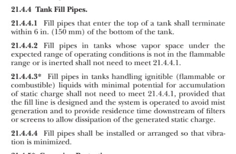
A paragraph in NFPA 30, if applicable:
NFPA_30_Note_d2ww6y.jpg
 
at 15m high, you probably need some guides off the tank wall to stop it moving about.

Also you may well get some sort of vaporisation as the liquid falls faster than the incoming fluid and hence pulls a vacuum or the liquid flashes off if its volatile.

Why are you entering at the top of the vessel?

MJC must have taken his medication today as that is a very good and succinct reply.

and hasn't mentioned an MBA in the post either which is not like him... ;-)

Remember - More details = better answers
Also: If you get a response it's polite to respond to it.
 
Dear LittleInch, MJCronin and JStephen,

Thank you so much for all your replies, really appreciate them.

Actually, the top inlet is something we normally do, but I just thought probably a dip pipe is required due to the height of the vessel itself.

Thanks again for your comments.
 
You should describe in details jurisdiction and liquid stored. What "dip" stands for - filling or gauging?

HSG 176 Storage of flammable liquids in tanks said:
Tank connections and fittings
118 Storage tank filling and emptying connections, and openings for dipping and venting, should be located at least 4 m from any source of ignition, building opening, trench or depression. Any drain in the vicinity should be either fitted with an interceptor or routed to an appropriate waste collection/treatment facility.
122 The end of the tank filling line should extend below the lowest normal operating level of the liquid to minimise the generation of static electricity from splash filling. To prevent siphoning, the line should be self draining. Where separate lines are used for filling and emptying, a liquid seal can be maintained by ending the discharge line at least 150 mm above the bottom of the filling line. To minimise the risk of tank leakage, it is preferable for lines to enter the tank at the top. This may not always be reasonably practicable, particularly for large vertical tanks, which are normally filled through a low-level nozzle.
123 All dip rods and tubes should be earthed and, where appropriate, an earthing lead for connection to a road tanker should be fitted. See PD IEC/TS 60079-32-1.
Dipping
138 Where gauging is done by dip rods, a suitable dip tube should be provided, with the dipping rod substantially smaller in diameter than the dip tube to minimise measurement errors. Dipping should not be done through open manholes.
139 Dipsticks are potential sources of ignition in that they may produce frictional heating or sparking, or static electricity. They should be made of non-sparking alloys and are earthed. Further guidance may be found in Energy Institute Model Code of Safe Practice Part 21: Guidelines for the control of hazards arising from static electricity.
140 Manual dipping is not as accurate as an automatic gauge but provides an adequate estimate of the contents. Each tank should have its own calibrated dipstick, not to be used for other tanks. It may be necessary to protect the bottom of the tank to avoid damage from repeated dipping.
141 Dipsticks for large tanks are difficult to handle. Dip tapes may be an alternative. They measure depth and are used with calibration tables for individual tanks.
 
Status
Not open for further replies.

Part and Inventory Search

Sponsor